A needle screw

A lead screw and needle roller technology, applied in the direction of transmission, belt/chain/gear, mechanical equipment, etc., can solve the problems of poor monitoring accuracy of lead screw movement, poor bearing capacity of ball screw, etc., to achieve convenient replacement, improve Radial bearing capacity, the effect of increasing the contact area

Inactive Publication Date: 2018-11-02
SUZHOU YASIKE PRECISION CNC CO LTD
View PDF7 Cites 0 Cited by
  • Summary
  • Abstract
  • Description
  • Claims
  • Application Information

AI Technical Summary

Problems solved by technology

[0006] The technical problem to be solved by the present invention is: to overcome the problems of poor bearing capacity of the ball screw and poor monitoring accuracy of the movement of the screw in the prior art, and to provide a needle screw with a displacement monitoring mechanism

Method used


Image

  • A needle screw
  • A needle screw

Examples


Embodiment Construction

[0027] The present invention is described in further detail now in conjunction with accompanying drawing. These drawings are all simplified schematic diagrams, which only illustrate the basic structure of the present invention in a schematic manner, so they only show the configurations related to the present invention.

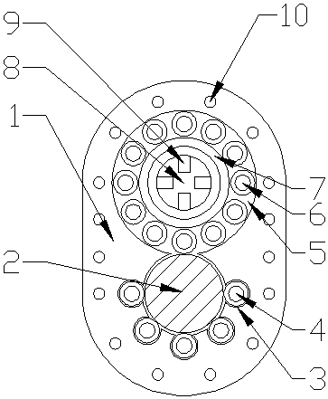
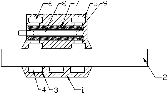
[0028] like figure 1 and figure 2 As shown, the present invention is a needle screw, which mainly includes a screw 2 and a sliding sleeve 1 sleeved on the screw 2;

[0029] Wherein the sliding sleeve 1 includes a sliding hole for passing through the lead screw 2, and two sets of stroke roller mechanisms and two sets of supporting roller mechanisms are arranged in the sliding sleeve 1;

[0030] Wherein the support roller mechanism includes a number of rotating grooves 3 arranged in an array along the inner wall of the sliding hole. The array radian of the rotating grooves 3 is greater than or equal to 180°. A needle roller A4 is arranged in the rotating groo...


PUM


Abstract

The invention relates to a rolling needle lead screw. The rolling needle lead screw comprises a lead screw and a slide sleeve, wherein the slide sleeve coats the lead screw, and has a slide hole; the slide sleeve comprises multiple travel roller mechanisms and multiple support roller mechanisms arranged along the inner wall of the slide hole; the support roller mechanisms comprise multiple rotating grooves arranged along the inner wall of the slide hole in an array form; rolling columns A are rotationally embedded in the rotating grooves; one sides of the rolling columns A are embedded in a spiral groove of the lead screw; the travel roller mechanisms comprise an annular slide groove formed in the slide sleeve; multiple rolling columns B are embedded in the slide groove; an opening communicated with the slide hole is formed in the slide groove; the rolling columns B are contacted with the spiral groove of the lead screw through the opening; the travel roller mechanisms comprise transparent support rings arranged on the annular inner wall of the slide groove; and the middle parts of the transparent support rings are fixed with a laser displacement sensor for monitoring the moving speed of an array of the rolling columns B.

Description

technical field [0001] The invention relates to a needle screw, which belongs to the field of conversion mechanisms for driving directions used in precision machinery. Background technique [0002] Generally speaking, the screw is divided into screw screw and ball screw according to the accuracy. The ball screw has better precision than the screw with sliding friction structure such as thread because of the good fit between the ball and the screw. However, compared with the surface contact of the threaded screw, the multi-point contact of the ball screw itself has many disadvantages; [0003] 1. The bearing capacity of the ball screw is not only affected by the strength of the screw itself, but when the bearing capacity of the ball is too large, the screw will be stuck and slipped due to uneven friction distribution, which will seriously affect the performance of the screw. normal work. [0004] 2. After the ball screw is loaded and disassembled with heavy objects for a lo...

Claims


Application Information

Patent Timeline
Patent Type & Authority Patents(China)
IPC IPC(8): F16H25/22
CPCF16H25/2015F16H25/2247F16H25/2266
Inventor 马峻孙建明
Owner SUZHOU YASIKE PRECISION CNC CO LTD
Why Eureka
Try Eureka