One-dimensional micrometric displacement device

A micro-displacement, No. 1 technology, applied to the parts of the instrument, instruments, etc., can solve the problems of small radial stiffness of the flexible hinge, difficulty in accurately controlling the output, and small radial bearing capacity, and achieve precise displacement control output, diameter The effect of large radial bearing capacity and improved radial stiffness

Inactive Publication Date: 2011-09-21
HARBIN INST OF TECH
View PDF0 Cites 0 Cited by
  • Summary
  • Abstract
  • Description
  • Claims
  • Application Information

AI Technical Summary

Problems solved by technology

[0009] The present invention aims to solve the problems of the existing micro-displacement devices, such as the small radial stiffness of the flexible hinge, the small radial bearing capacity, and the difficulty in precisely controlling the output, thereby providing a one-dimensional micro-displacement device

Method used


Image

  • One-dimensional micrometric displacement device
  • One-dimensional micrometric displacement device
  • One-dimensional micrometric displacement device

Examples


specific Embodiment approach 1

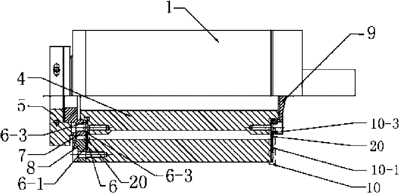
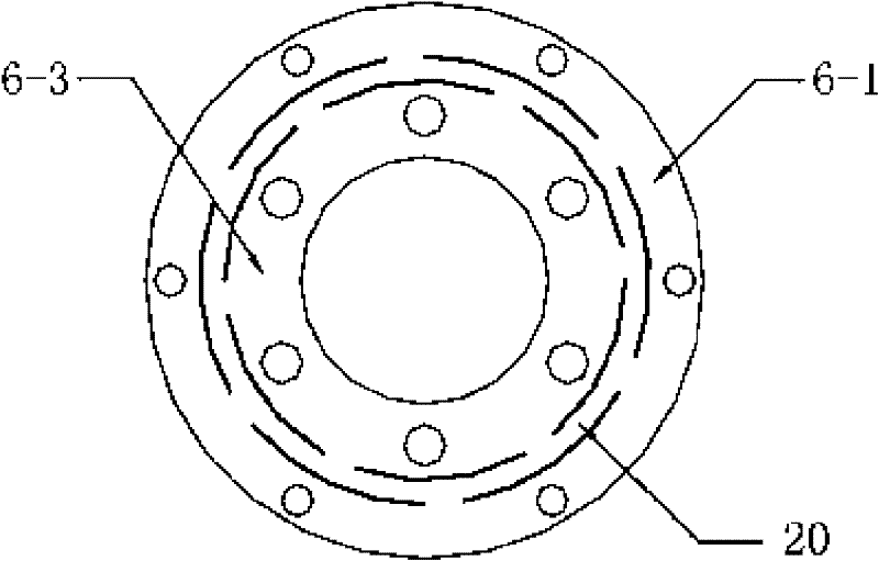
[0013] Specific implementation mode 1. Combination figure 1 , image 3 and Figure 4 Illustrate this specific embodiment, one-dimensional micro-displacement device, it comprises base 1, front end cover 7 and rear end cover 9, and it also comprises workbench 5, front strain gauge 6 and rear strain gauge 10 and connecting shaft 4, described The connecting shaft 4 is located in the working hole of the base 1, and the front strain gauge 6 is composed of a No. 1 outer ring 6-1, a strain ring 20 and a No. 1 inner ring 6-3; the No. 1 inner ring 6-3, the strain ring 20 is coaxial with the No. 1 outer ring 6-1, and the strain ring 20 is flexibly connected between the No. 1 outer ring 6-1 and the No. 1 inner ring 6-3; the rear strain gauge 10 is composed of the No. 2 outer ring 10-1, The strain ring 20 is composed of the rear strain inner ring 10-3, the No. 2 inner ring 10-3, the strain ring 20 and the No. 2 outer ring 10-1 are coaxial, and the strain ring 20 is flexibly connected to ...

specific Embodiment approach 2

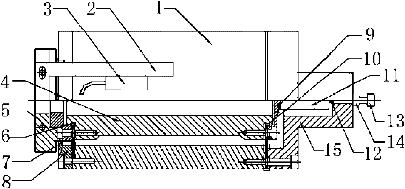
[0016] Embodiment 2. The difference between this embodiment and the one-dimensional micro-displacement device described in Embodiment 1 is that it also includes a piezoelectric ceramic sheet 11 and a piezoelectric ceramic sheet holder 15, and the piezoelectric ceramic sheet holder The seat 15 is a table body with a T-shaped groove in the center of the left end. The piezoelectric ceramic sheet 11 is located in the groove of the piezoelectric ceramic sheet holder 15. The left end surface of the piezoelectric ceramic sheet 11 is connected to the rear The end cover 9 is in close contact, and the right end face of the piezoelectric ceramic sheet 11 is in close contact with the groove bottom of the piezoelectric ceramic sheet holder 15; the left end surface of the piezoelectric ceramic sheet holder 15 is fixed on the on base 1.

[0017] In this embodiment, by applying a certain amount of voltage to the piezoelectric ceramic 11, the piezoelectric ceramic is stretched, and the rear en...

specific Embodiment approach 3

[0018] Embodiment 3. The difference between this embodiment and the one-dimensional micro-displacement device described in Embodiment 2 is that it also includes a steel ball 12, which is located on the right end surface of the piezoelectric ceramic sheet 11 and the piezoelectric ceramic Between the groove bottoms of the card holder 15.


PUM


Abstract

The invention discloses a one-dimensional micrometric displacement device, and relates to a micrometric displacement device, solving the problems of small radial stiffness of a flexible hinge, small radial bearing capacity and difficulty of accurately controlled output of the existing micrometric displacement device. The connecting shaft of the one-dimensional micrometric displacement device is positioned in a working hole of a base; a front strain gage and a rear strain gage are arranged in parallel; a first inner ring and a second inner ring are respectively fixed in shoulders at two ends of the connecting shaft; a front end cover and a rear end cover are respectively connected with the shoulders of the connecting shaft through the first inner ring and the second inner ring; the first inner ring and the second inner ring are respectively fixed at two ends of the base; and the second inner ring is fixedly connected with the rear end cover. The device of the invention can be widely applicable to the occasions in ultra-precision finishing for provision of error compensation, precise microscale feed and the like.

Description

technical field [0001] The invention relates to a micro-displacement device. Background technique [0002] Precision positioning technology is one of the key technologies in precision manufacturing, precision measurement and precision drive. High-tech scientific and technological research results, interdisciplinary comprehensive design, and the application of high-precision technology make precision positioning technology break through the traditional optical, mechanical, and electrical frameworks, and are widely used in micro-mechanical manufacturing, ultra-precision processing, semiconductor technology, microscope technology, biological In the fields of engineering, data storage technology, life and medical science, integrated circuit manufacturing, optical adjustment, scanning tunneling microscope, operation and assembly of micro parts, semiconductor manufacturing and equipment, and optoelectronics. As an indispensable part in the research of precision positioning techno...

Claims


Application Information

Patent Timeline
Patent Type & Authority Patents(China)
IPC IPC(8): G12B5/00
Inventor 李国孙涛张龙江董申
Owner HARBIN INST OF TECH
Why Eureka
Try Eureka