Single fastener strut top mount and method of optimizing same

a single fastener and strut technology, applied in the direction of shock absorbers, adaptive control, instruments, etc., can solve the problem of difficult use of this design on multiple vehicle applications, and achieve excellent vibration isolation

Inactive Publication Date: 2013-01-08
GM GLOBAL TECH OPERATIONS LLC
View PDF29 Cites 17 Cited by
  • Summary
  • Abstract
  • Description
  • Claims
  • Application Information

AI Technical Summary

Benefits of technology

[0008]The present invention is a single fastener, compact strut top mount which is optimized in that its resilient response to jounce and rebound load rates is symmetrical and linear over a predetermined range of travel, is stiff radially, is tunable for various vehicle applications and provides excellent vibration isolation.
[0013]A soft initial load rate characteristic of the outer resilient element provides a desirable strut top mount displacement when the vehicle corner sprung weight is applied to the strut top mount. A high load rate in the steep portion of the force deflection curve offers favorable damper reaction to the vehicle body. Because the outer and inner resilient elements react in series to loads applied to the strut top mount by the strut shaft, the axial compliance contribution from the outer resilient element is minimized to make the resultant axial load rate of the strut top mount from the outer and inner resilient elements sufficiently high. This is achieved by ensuring that the outer resilient element of the strut top mount is loaded into the steep portion of its force deflection curve under the vehicle's curb weight.
[0014]A specific arrangement of the strut tower and outer resilient element enable this desired load rate shape. The outer resilient element has a nearly vertical section positioned within a corresponding nearly vertical tower side wall. The column of resilient material thereof acts primarily in shear to axially applied forces and provides the low initial load rate, while reacting mostly in compression to radially applied forces for high radial stiffness. A top section of the outer resilient element located adjoining the substantially horizontal tower top wall reacts vertically against the tower with a rolling action and is ultimately mostly in compression for high durability and high load rate.
[0015]The top convolute portion of the convolutes provide a rolling engagement with the tower top wall, and at outer periphery of the outer resilient element acts primarily in shear to axially applied forces and provides a low initial load rate, while reacting mostly in compression to radially applied forces with respect to the tower side wall. This engagement feature provides a smooth, continuous transition between the soft shear and stiff compression sections of the outer resilient element and eliminates potential slapping noises by avoiding intermittent contact between flat surfaces. This outer resilient element geometric arrangement also enables a high radial load rate that adduces a favorable vehicle steering feel.
[0016]Several advantages of the strut top mount according to the present invention include: contact between the outer resilient element and the underside of the strut tower is provided between the extremes of jounce and rebound, thereby eliminating noise and providing high durability; a large gap between the retention washer and the strut tower of the vehicle body structure provides unimpeded damper isolation and sufficient freedom from contact with the strut tower during coning motion of the strut top mount during steering action of the vehicle suspension; a sufficiently high strut top mount axial rate for effective damper reaction (an overly high axial rate is undesirable for vibration isolation); and a high strut top mount radial rate for favorable vehicle steering feel. Further, since the strut top mount according to the present invention is quite insensitive to vehicle mass, it is suitable for use on a range of vehicle applications having differing vehicular masses.
[0017]Accordingly, it is an object of the present invention to provide a single fastener, compact strut top mount which has an optimized resilient response to jounce and rebound.

Problems solved by technology

The latter loadpath arrangement does not enable use of monotube struts (monotube struts route the jounce bumper loads up through the strut rod and, therefore, the strut top mount thereof requires an appropriately high load capacity in the damper rod load-path to handle them, whereby this is possible only for a single path strut top mount or a dual path strut top mount with the bumper and damper loads combined into the same path).
Additionally, the design height position of the prior art strut top mount 10, when loaded under vehicle curb weight, varies with vehicle mass, making it difficult to use this design on multiple vehicle applications (i.e., differing rubber chemistry or durometer of each of the inner and outer rubber elements is required, wherein the outer rubber element is adjusted to vehicle mass to provide a desired retention washer gap with respect to the strut tower, and the inner rubber element is tuned to adjust, somewhat, the mount rate).

Method used


Image

  • Single fastener strut top mount and method of optimizing same
  • Single fastener strut top mount and method of optimizing same
  • Single fastener strut top mount and method of optimizing same

Examples


Embodiment Construction

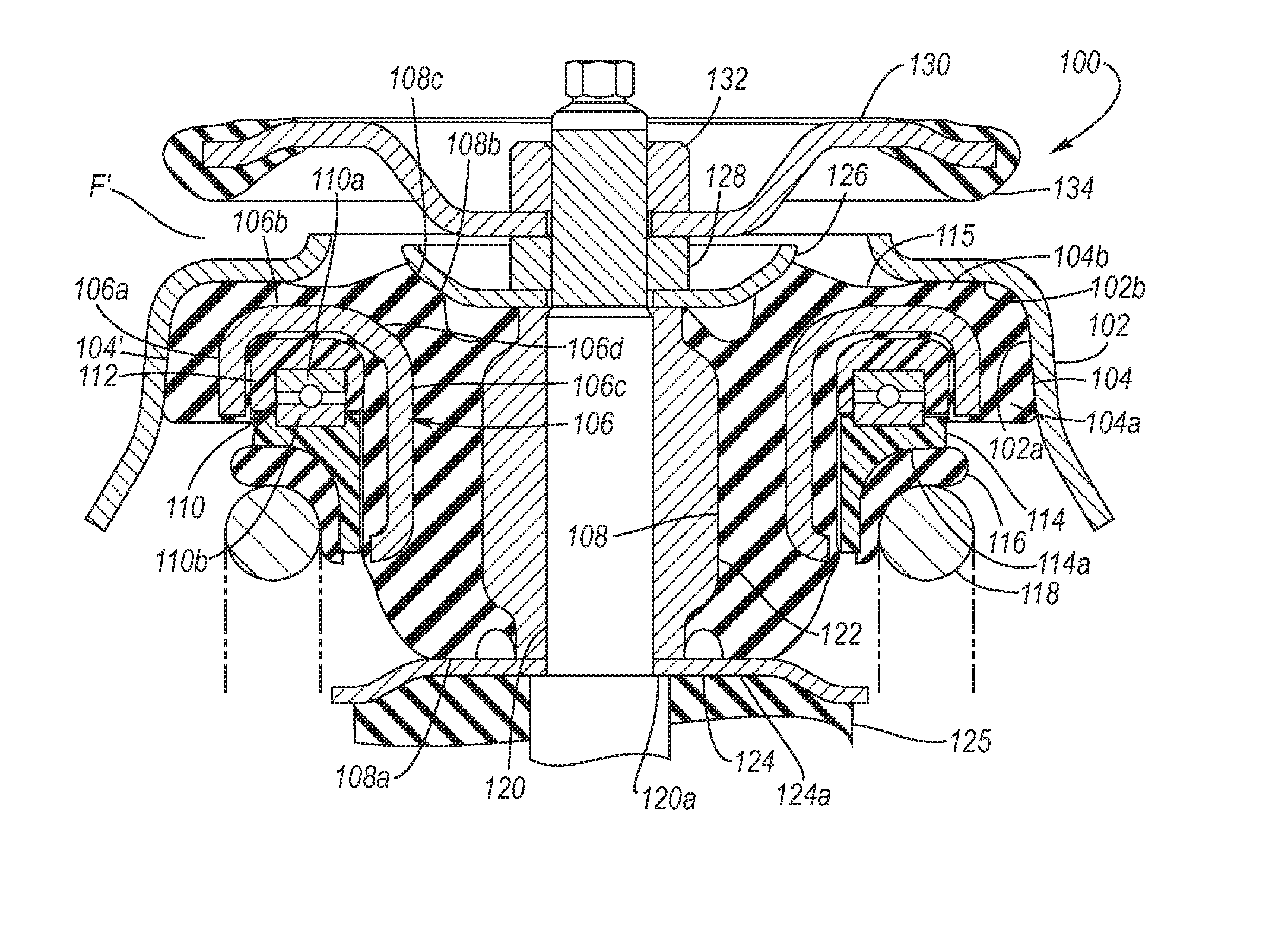
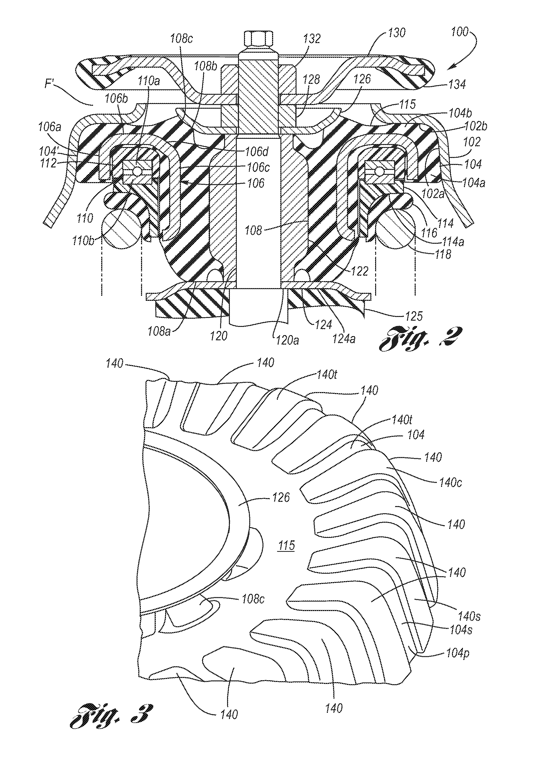
[0033]Referring now to the Drawing, FIGS. 2 through 6 depict views of the strut top mount according to the present invention, FIGS. 7 through 11 depict graphs used, according to the present invention, for optimizing the strut top mount according to the present invention, the method for which being summarized at FIG. 12.

[0034]Referring firstly to FIGS. 2 through 4 structural and functional aspects of the strut top mount 100 according to the present invention will be detailed.

[0035]A narrow, annular strut tower 102 is connected at its lower end (not shown) to structural members of the motor vehicle in a manner that is well known in the art. An annular outer resilient element 104 has a gently inclined outer surface 104′ which abuts (without adherence) the strut tower 102 at a tower side wall 102a. The outer resilient element 104 preferably has no metal insert (generally akin to 20 in FIG. 1), but this may be optionally included. An annular central bracket, having a U-shape in cross-sec...


PUM


Abstract

A strut top mount is optimized to provide a resilient response to jounce and rebound load rates that is symmetrical and linear over a predetermined range of travel. An annular tower is formed of the body structure. A central bracket has adhered thereto an outer resilient element that abuts the tower, and has adhered oppositely thereto an inner resilient element. A bearing is supported by the central bracket, and a spring seat is supported by the bearing. A sleeve is received by a strut shaft and adhered to the inner resilient element A lower washer abuts a lower end of the inner resilient element. An upper washer abuts an upper end of the inner resilient element. A retention washer is mounted onto the strut shaft, wherein a periphery thereof has a retention washer resilient element. The components are collectively tuned to provide the optimization.

Description

TECHNICAL FIELD[0001]The present invention relates to MacPherson strut-type motor vehicle suspension systems, and particularly to single fastener MacPherson strut top mounts.BACKGROUND OF THE INVENTION[0002]Motor vehicle suspension systems are configured so that the wheels are able to follow elevational changes in the road surface as the vehicle travels therealong. When a rise in the road surface is encountered, the suspension responds in “jounce” in which the wheel is able to move upwardly relative to the frame of the vehicle. On the other hand, when a dip in the road surface is encountered, the suspension responds in “rebound” in which the wheel is able to move downwardly relative to the integrated body / frame structure of the vehicle. In either jounce or rebound, a spring (i.e., coil, leaf, torsion, etc.) is incorporated with the body structure in order to provide a resilient response to the respective vertical movements of the wheel with regard to the vehicle body structure. Howe...

Claims


Application Information

Patent Timeline
Patent Type & Authority Patents(United States)
IPC IPC(8): F16F9/38F16F9/36
CPCB60G15/068B60G2202/31
Inventor WINOCUR, PAUL A.
Owner GM GLOBAL TECH OPERATIONS LLC
Why Eureka
Try Eureka