Bearing for a motor vehicle

a technology for motor vehicles and bearings, applied in the direction of shock absorbers, machine supports, transportation and packaging, etc., can solve the problems of increasing axial stiffness, and achieve the effect of increasing radial stiffness

Inactive Publication Date: 2007-06-26
ZF FRIEDRICHSHAFEN AG
View PDF15 Cites 13 Cited by
  • Summary
  • Abstract
  • Description
  • Claims
  • Application Information

AI Technical Summary

Benefits of technology

[0007]According to the invention, the two undulated contours are not equidistant to each other, so that they do not have the same relative separation at each location along their longitudinal extent. As a result, a greater spread between the characteristic curves for axial stiffness, radial stiffness and torsional stiffness can be achieved; in particular, the radial stiffness can be adjusted more or less independently. For example, a bearing can be implemented which has a high axial stiffness and a high radial stiffness, while at the same time exhibiting a low torsional stiffness.
[0023]According to this embodiment, the outer sleeve forms an intermediate part, so that an additional increase in the radial stiffness can be achieved. The second outer sleeve can also be calibrated and, more particularly, can have on its outer surface a fifth undulated contour extending his longitudinal direction.

Problems solved by technology

However, this configuration would increase the axial stiffness in only one direction.

Method used


Image

  • Bearing for a motor vehicle
  • Bearing for a motor vehicle
  • Bearing for a motor vehicle

Examples


Embodiment Construction

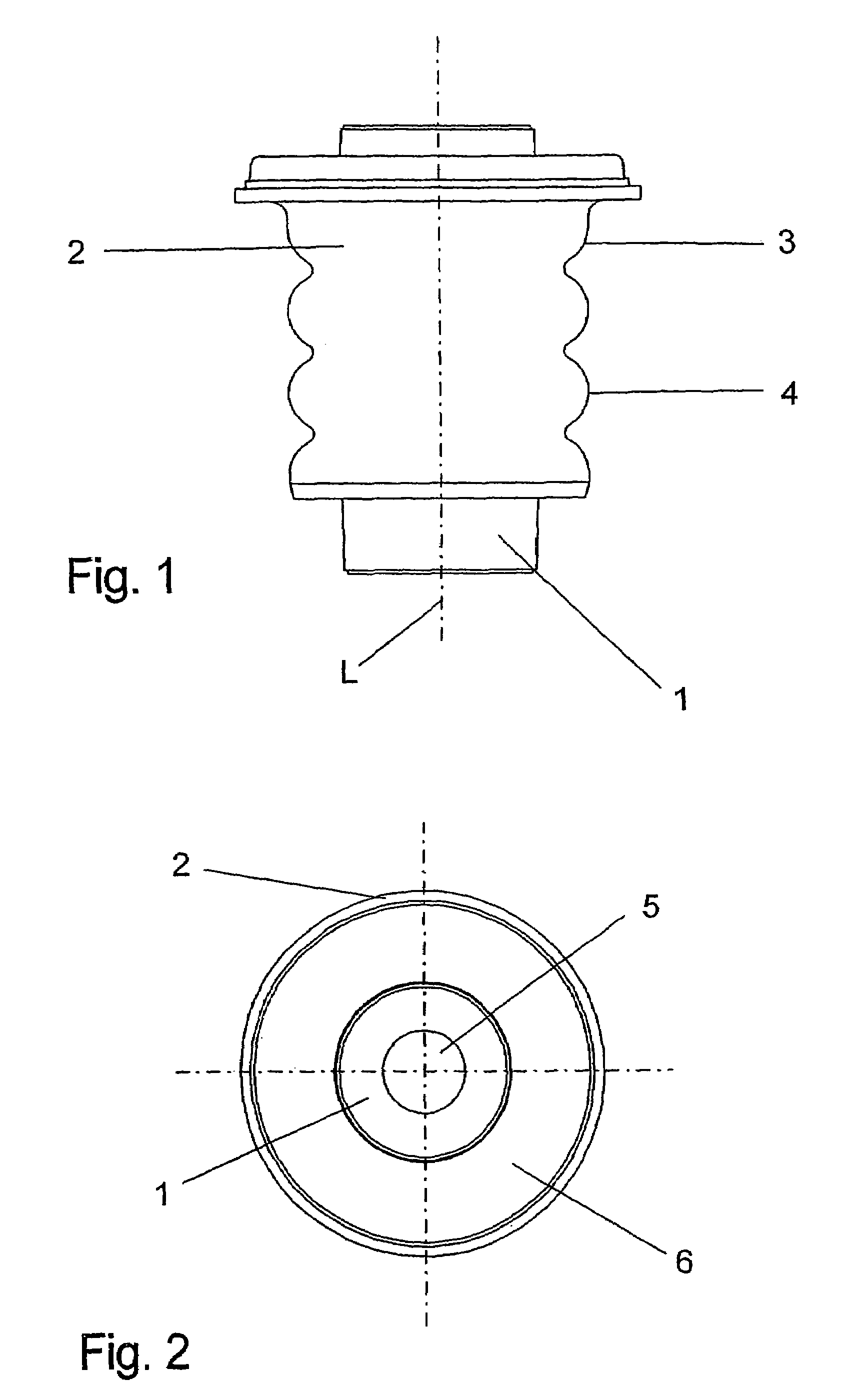
[0035]FIG. 1 shows in a side view the first embodiment of the bearing according to the invention, wherein L indicates the longitudinal axis of the bearing. In inner part 1 is here surrounded by an outer sleeve 2 which has an outer surface 3 with an undulated contour 4.

[0036]As seen in the top view of FIG. 2, the complete bearing is rotationally symmetric, with the inner part 1 and the outer sleeve 2 being arranged concentrically with respect to each other. The inner part 1 is formed as a sleeve and has a through bore 5. An elastomer body 6 is disposed between the inner part 1 and the outer sleeve 2, connecting the inner part 1 and the outer sleeve 2 with each other.

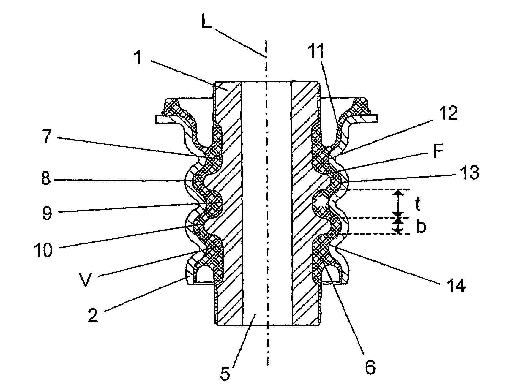
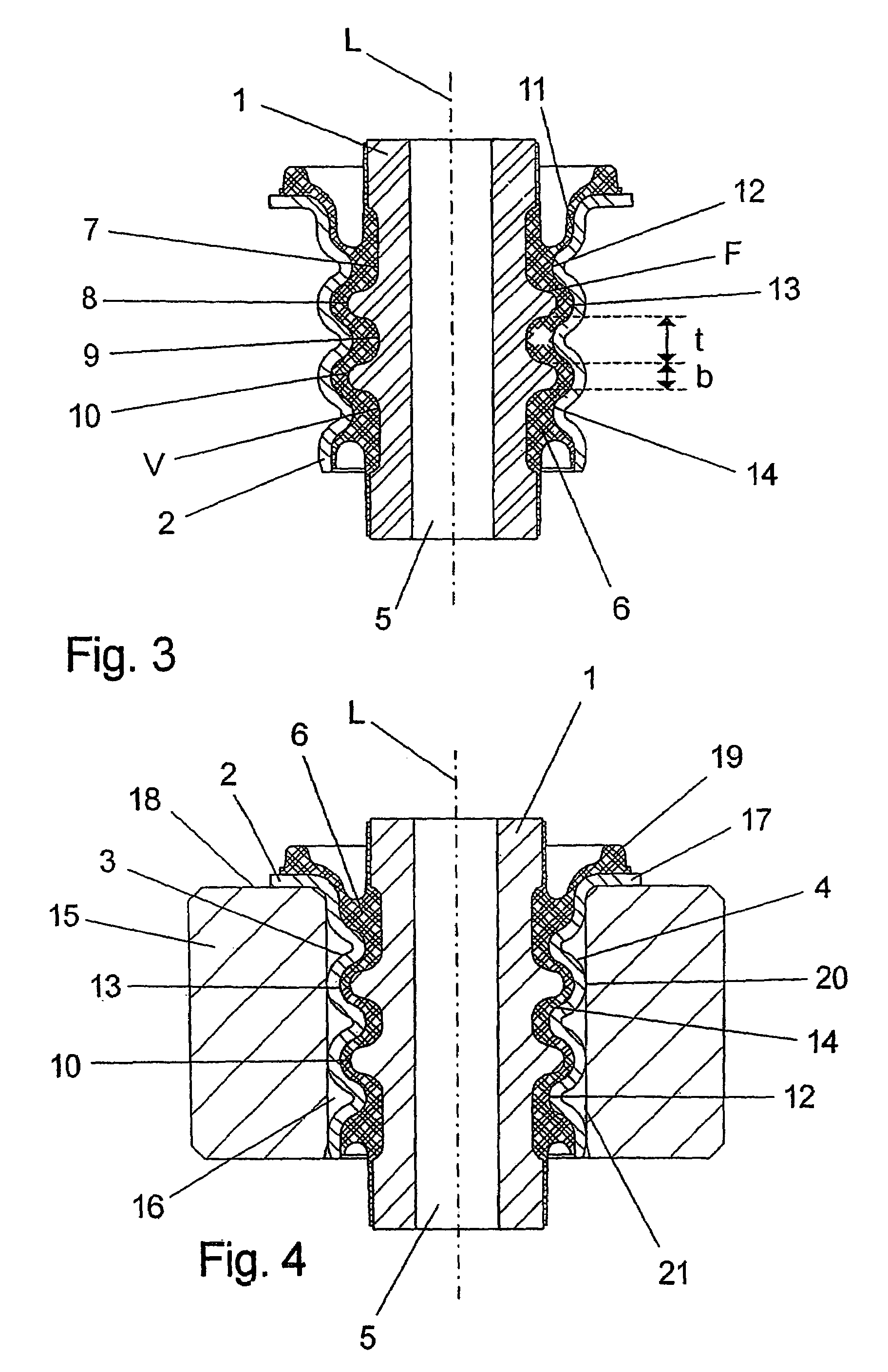
[0037]FIG. 3 shows a cross-sectional view of the first embodiment, wherein the outer surface 7 of the inner part 1 has two raised portions (wave crests) 8 extending toward the outer sleeve 2 and an intermediate indentation (wave trough) 9. As a result, an undulated contour 10 extending in the longitudinal direction L is f...


PUM


Abstract

Bearing for a motor vehicle, with an inner part 1 with an outer surface 7 having a first undulated contour 10 extending in a longitudinal direction L, an outer sleeve 2 surrounding the inner part 1 and having an inner surface 11 with a second undulated contour 14 extending in the longitudinal direction L, an undulated elastomer body 6 disposed between the two corrugated contours 10, 14 and extending in the longitudinal direction L. The elastomer body 6 connects the inner part 1 with the outer sleeve 2. The two undulated contours 10, 14 do not run equidistant relative to each other.

Description

BACKGROUND OF THE INVENTION[0001]The invention is directed to a bearing for a motor vehicle, with an inner part with an outer surface having a first undulated contour extending in a longitudinal direction, an outer sleeve surrounding the inner part with an inner surface having a second undulated contour extending in the longitudinal direction, an undulated elastomer body disposed between the two corrugated contours and extending in the longitudinal direction, whereby the elastomer body connects the inner part with the outer sleeve.[0002]Bearings with an inner part, an outer sleeve surrounding the inner part and an elastomer body arranged between the inner part and the outer sleeve and connecting the inner part with the outer sleeve are known in the art, but disadvantageously exhibit a design-limited spread between the radial stiffness and the axial stiffness. For a high radial stiffness, the values for the axial stiffness are limited due to the high calibration, wherein the term “ca...

Claims


Application Information

Patent Timeline
Patent Type & Authority Patents(United States)
IPC IPC(8): B60G11/22F16F1/44F16F1/38
CPCF16F1/3863
Inventor SCHNAARS, WOLFGANGHEUER, KARL
Owner ZF FRIEDRICHSHAFEN AG
Why Eureka
Try Eureka