
Image processing apparatus and an image processing program

An image processing device and image processing technology, applied in image data processing, image communication, image enhancement, etc., can solve problems such as unclearness and low contrast, and achieve the effect of emphasizing contrast

Active Publication Date: 2015-09-23
SHIMADZU CORP
View PDF9 Cites 2 Cited by
  • Summary
  • Abstract
  • Description
  • Claims
  • Application Information

AI Technical Summary

Problems solved by technology

[0002] Generally, when an image includes a bright area (area with high luminance value) and a dark area (area with low luminance value), there is a di

Method used


Image

  • Image processing apparatus and an image processing program
  • Image processing apparatus and an image processing program
  • Image processing apparatus and an image processing program

Examples


Example Embodiment

[0037] Hereinafter, embodiments of the present invention will be described with reference to the drawings.

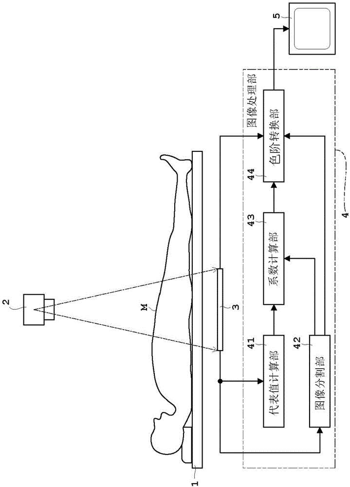
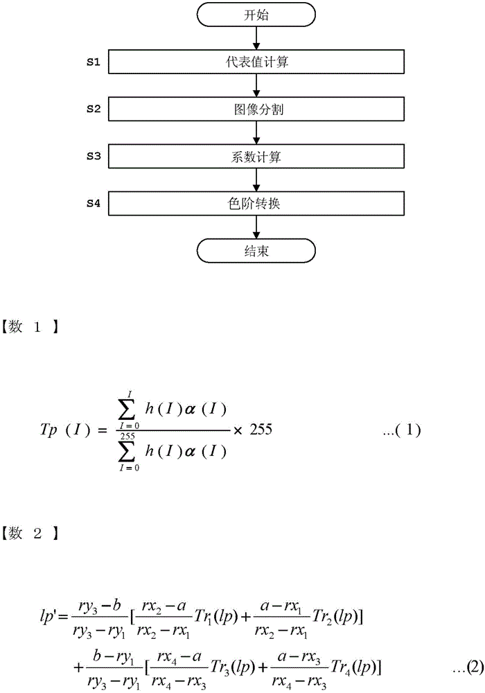
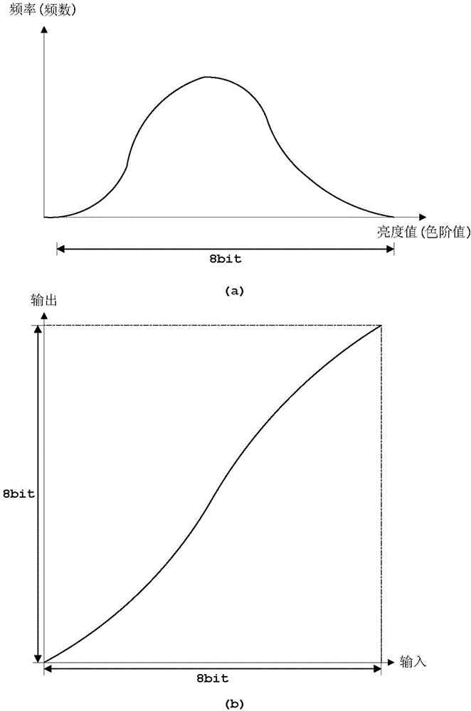
[0038] figure 1 Is a block diagram of the radiographic imaging device according to the embodiment, figure 2 Is a flowchart showing the flow of a series of image processing involved in the embodiment, image 3 It is a schematic diagram of brightness histogram and color scale conversion (tone curve), Figure 4 Is an example of the weighting coefficient when the contrast is emphasized, Figure 5 Is an example of weighted addition used to calculate the gradation conversion value, Image 6 It is a flowchart showing the flow of processing by the gradation conversion unit. In this embodiment, as the object of image processing, a digital image (input image), which is a radiographic image obtained by a radiographic imaging device, is taken as an example for description, and as the color scale of pixels in the input image and image processing The corresponding relationship related ...


PUM


Abstract

A representative value calculator calculates a representative value which is a luminance value representing a main inspection object area from an input image. On the other hand, an image divider divides an image area of the input image, and sets a plurality of divided ranges. A factor calculator calculates a tone conversion factor for enhancing or suppressing contrast adjacent the representative value calculated by the representative value calculator for each area (each divided area) divided by the image divider. A tone converter converts the tone of each pixel of the input image based on the tone conversion factor for the range divided by the image divider, which range includes a pixel for image processing, and ranges adjacent that range. As a result, the contrast of the area for which enhancement is desired can be enhanced optimally.

Description

technical field [0001] The present invention relates to an image processing device and an image processing method for processing an input image as an input digital image, and in particular relates to a technology of color scale conversion. Background technique [0002] Generally, when an image contains bright areas (areas with high luminance values) and dark areas (areas with low luminance values), there is a difference in luminance between the two areas, but the difference in luminance disappears within each area. , The contrast tends to be small and unclear. For this problem, there is known a method of generating a luminance histogram of an image whose horizontal axis is luminance value (gradation value) and whose vertical axis is frequency (frequency), and performing gradation to make the distribution of luminance uniform. By converting, the contrast of the gradation with a large number of elements (frequency of the same luminance value) is emphasized. Contrast can be e...

Claims


Application Information

Patent Timeline
IPC IPC(8): G06T5/00G06T7/00
CPCG06T7/408G06T7/0081G06T5/00G06T2207/10024G06T5/40G06T5/008G06T2207/20021H04N1/4074
Inventor 大野义典
Owner SHIMADZU CORP
Learn More