
Image processor and pattern recognition apparatus using the image processor

a pattern recognition apparatus and image processor technology, applied in image enhancement, image analysis, instruments, etc., can solve the problems of difficult to recognize the alignment mark from the surface image with reliability, the part of the alignment mark cannot be extracted with a high degree of accuracy, so as to achieve the effect of accurate extraction of only the pattern and highlighting the contras

Inactive Publication Date: 2006-05-02
MATSUSHITA ELECTRIC WORKS LTD
View PDF3 Cites 12 Cited by
  • Summary
  • Abstract
  • Description
  • Claims
  • Application Information

AI Technical Summary

Benefits of technology

[0007]Therefore, a primary concern of the present invention is to provide an image processor having the capability of providing, from a surface image of an object having a pattern, a processed image having a distinct contrast between the pattern and a background.
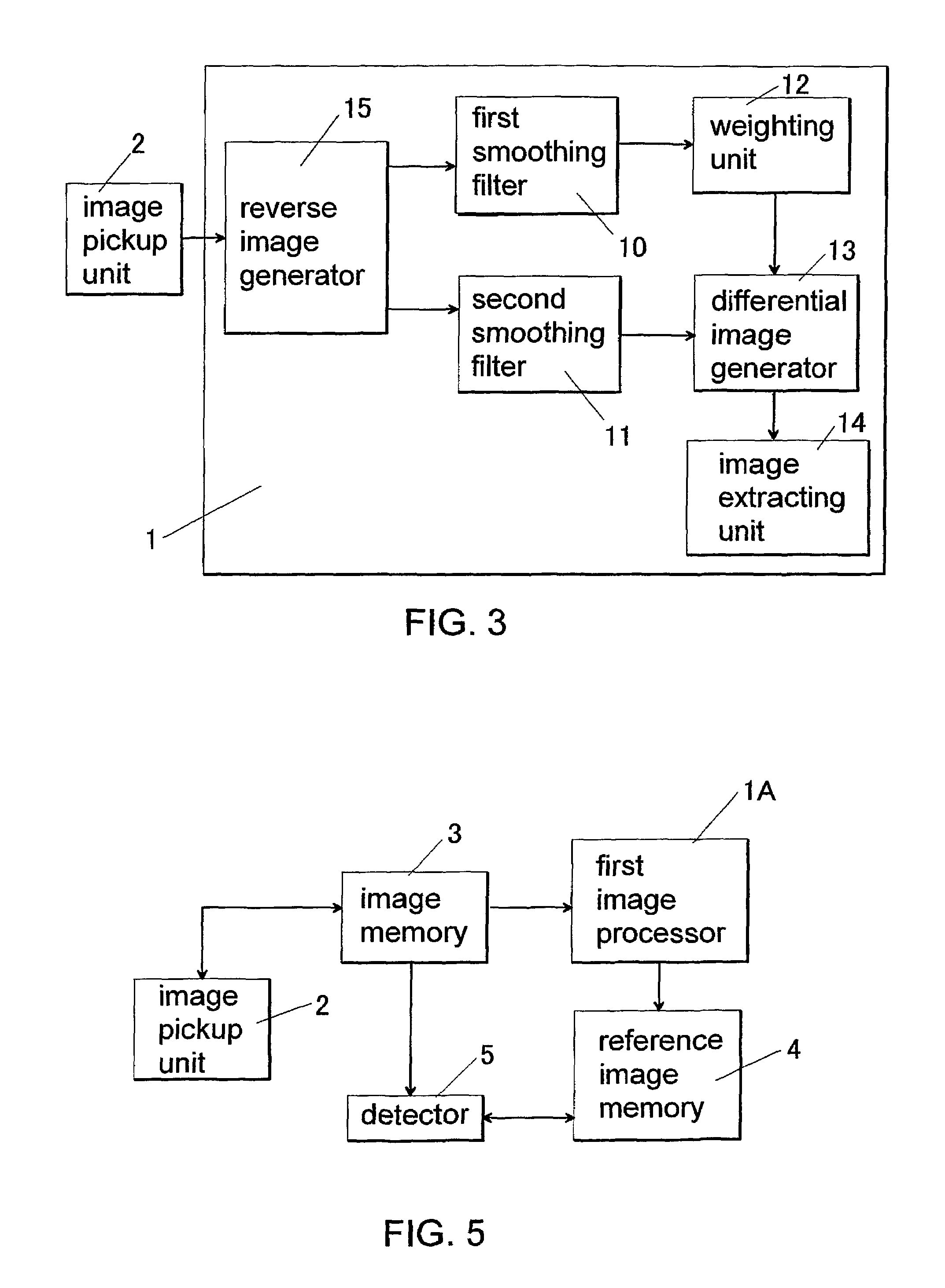
[0015]It is preferred that the image processor described above further comprises a reverse image generator for generating a reverse image of the surface image. The reverse image generator determines a concentration value of each of pixels of the reverse image by subtracting a concentration value of each of pixels of the surface image of the object from a maximum concentration value of the surface image. As a result, the first and second smoothing filters respectively generate the first and second smoothed images from the reverse image. When it is required to generate the processed image from the surface image that includes a pattern having a higher brightness than the background, it is possible to provide the processed image having the distinct contrast, as in the above case of generating the processed image from the surface image that includes a pattern having a lower brightness than the background.

Problems solved by technology

However, this process of generating the binary image has a problem that when a concentration (brightness) of the alignment mark is not constant in the surface image, a part of the alignment mark can be not extracted, or a part of the background is erroneously extracted together with the alignment mark.
As a result, since the generated binary image includes incorrect image data, the alignment mark can not be recognized from the binary image with a high degree of accuracy.
Such a problem will become a reality in the case of recognizing an alignment mark given on an optically transparent or translucent substrate in a manufacturing process of liquid-crystal display devices.
For example, as shown in FIGS. 12A and 12B or FIGS. 13A and 13B, when a surface image 30 of the substrate having an alignment mark AM (“+” mark) is taken through a translucent film placed on the substrate by an image pickup unit, it is very difficult to recognize the alignment mark from the surface image with reliability because of a poor contrast between the alignment mark and the background, and the influence of undesired air bubbles AB trapped between the translucent film and the substrate.
However, there is a case that the recognition accuracy can not be sufficiently improved even when the recognition treatment is repeatedly performed.
This brings a reduction in production efficiency and an increase in production cost.
In addition, when an air bubble(s) AM is trapped at the vicinity of the alignment mark between the translucent film and the substrate, there is a case that light irradiated to the substrate to take the surface image by the image pickup unit is reflected at a surface of the translucent film inflated by the air bubble, so that a part of the alignment mark is lost from the surface image.
Even when the alignment mark is recognized, the reliability of recognition results will be low.

Method used


Image

  • Image processor and pattern recognition apparatus using the image processor
  • Image processor and pattern recognition apparatus using the image processor
  • Image processor and pattern recognition apparatus using the image processor

Examples


Embodiment Construction

[0046]The followings are preferred embodiments of the present invention. However, these embodiments do not limit the scope of the present invention.

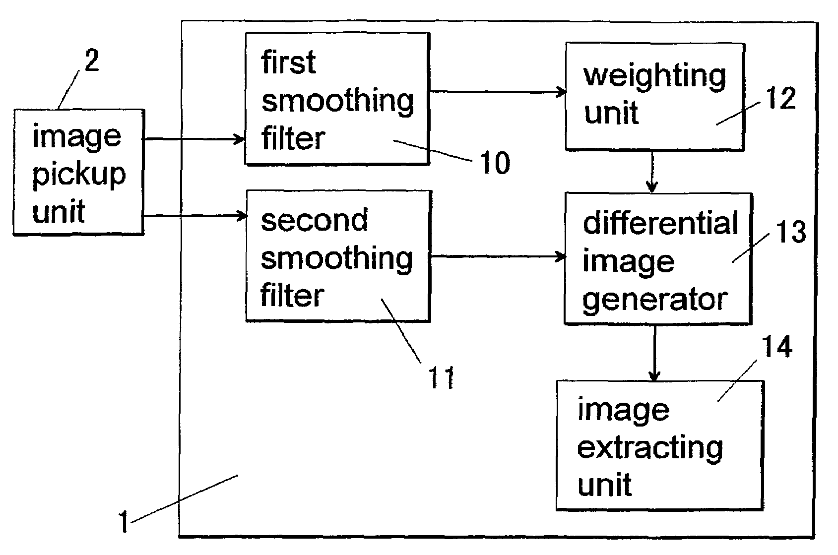
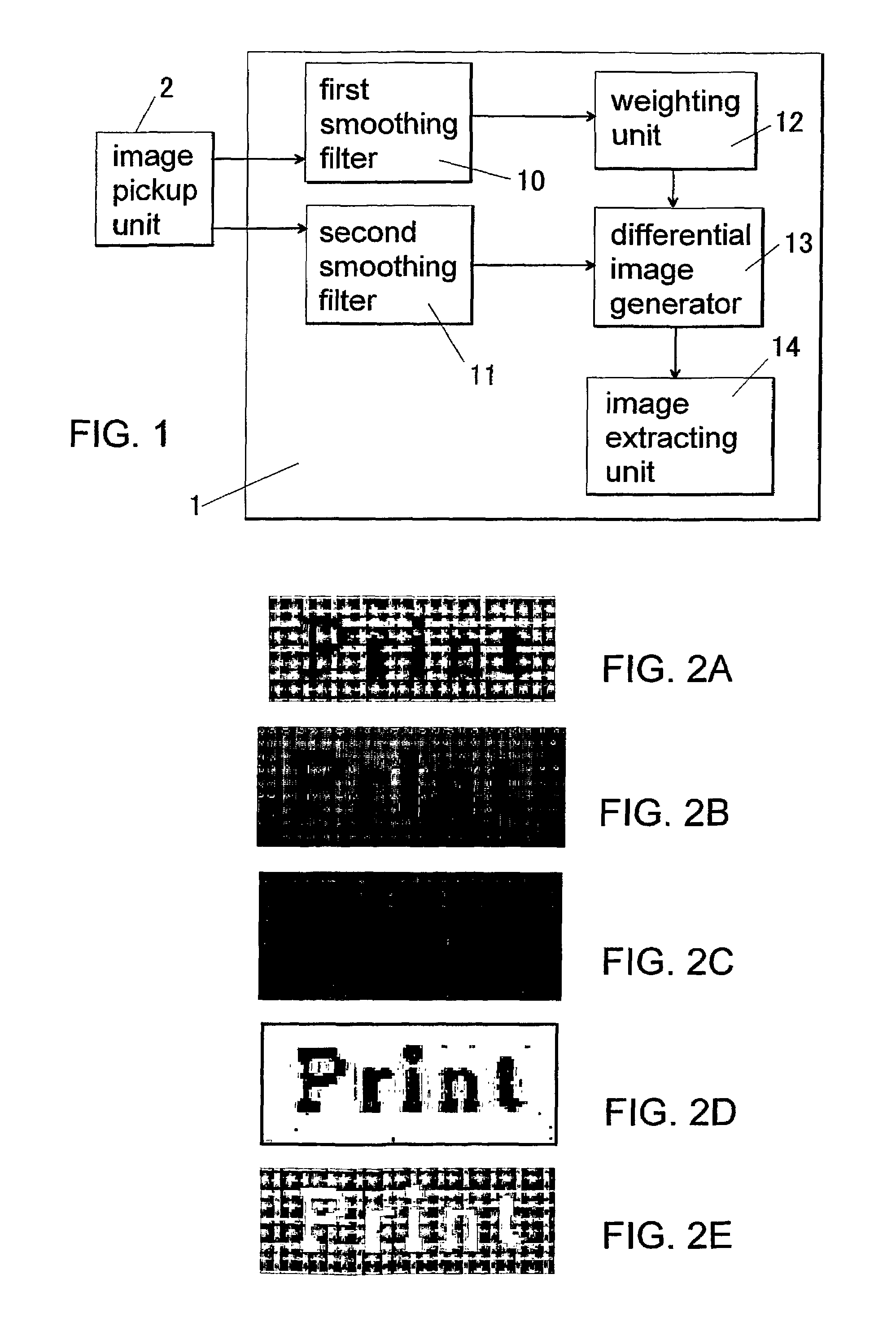
[0047]An image processor 1 of the first embodiment of the present invention is explained referring to FIG. 1 to FIG. 3. An object used in this embodiment has an alignment mark having a lower brightness than a background. A surface image including the alignment mark of the object can be obtained by a conventional image pickup unit 2 such as TV cameras.

[0048]As shown in FIG. 1, the surface image taken by the image pickup unit 2 is sent to each of first and second smoothing filters (10, 11) of the image processor 1. The first smoothing filter 10 determines, with respect to each of pixels of the surface image, a mean concentration value for the pixel and neighbor pixels in a first region defined around the pixel to generate a first smoothed image. As the first region, a square region “(2n1+1)×(2n1+1)” can be used, wherein “n1” is an integer....


PUM


Abstract

An image processor for generating, from a surface image of an object having a pattern, a processed image having a distinct contrast between the pattern and a background, is provided. This image processor comprises a first smoothing filter for generating a first smoothed image; a second smoothing filter for generating a second smoothed image; a weighting unit for multiplying each of pixel values of the first smoothed image by a weight coefficient of 1 or more to determine a weighted pixel value; a differential image generator for subtracting each of weighted pixel values provided by the weighting unit from a pixel value of a corresponding pixel of the second smoothed image to generate a differential image; and an image extracting unit for extracting pixel values having the positive sign from the differential image to obtain the processed image. For example, this image processor can be utilized in a pattern recognition apparatus.

Description

TECHNICAL FIELD[0001]The present invention relates to an image processor for providing, from a surface image of an object having a pattern such as letters or symbols, a processed image having a distinct contrast between the pattern and a background, and a pattern recognition apparatus with the image processor, which is preferably used to accurately detect an alignment mark on an optically transparent or translucent substrate in a manufacturing process of liquid-crystal display devices.BACKGROUND ART[0002]In the past, an image processing technique has been utilized to recognize an alignment mark such as letters or symbols given on an object to be inspected. In this method, a surface image (a gray-scale image) of the object is converted to a binary image according to an appropriate threshold value. Since the alignment mark has a different concentration from a background, pixels corresponding to the alignment mark can be extracted from the pixels of the background.[0003]However, this p...

Claims


Application Information

Patent Timeline
Patent Type & Authority Patents(United States)
IPC IPC(8): G06K9/68G06T5/00G06T5/50G06V30/10G06V30/162
CPCG06K9/38G06T5/004G06T7/0081G06T7/0097G06T2207/30204G06T2207/20144G06T2207/20224G06T7/11G06T7/174G06T7/194G06V30/10G06V30/162G06T5/75G06V10/40
Inventor HASHIMOTO, YOSHIHITOIKEDA, KAZUTAKA
Owner MATSUSHITA ELECTRIC WORKS LTD
Learn More