Braking unit
A technology of braking unit and control unit, which is applied in the direction of electric motor/converter plug, etc., can solve the problems of non-adjustable braking voltage, blown fuse, irreversible braking unit, etc., so as to overcome the inconvenience of control and solve the effect of the problem
- Summary
- Abstract
- Description
- Claims
- Application Information
AI Technical Summary
Problems solved by technology
Method used
Image

Examples
Embodiment Construction
[0021] In order to clearly understand the technical solution of the present invention, its detailed structure will be presented in the following description. Obviously, the implementation of the embodiments of the invention is not limited to specific details familiar to those skilled in the art. The preferred embodiments of the present invention are described in detail below, and there may be other implementations besides those described in detail.
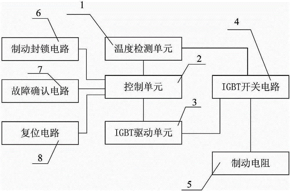
[0022] see figure 1 , a brake unit, comprising: a temperature detection unit 1, a control unit 2, an IGBT drive unit 3, an IGBT switch circuit 4, a brake resistor 5, and a power supply unit; wherein: the IGBT switch circuit 4 is used to control the brake resistor 5 The working state of the control unit 2 is used to control the working state of the IGBT switch circuit. The signal output port of the control unit 2 is electrically connected to the IGBT switch circuit 4 through the IGBT drive unit 3. The temperature detection unit 1 ...
PUM
 Abstract
Description
Claims
Application Information
 - R&D
- Intellectual Property
- Life Sciences
- Materials
- Tech Scout
- Unparalleled Data Quality
- Higher Quality Content
- 60% Fewer Hallucinations
Browse by: Latest US Patents, China's latest patents, Technical Efficacy Thesaurus, Application Domain, Technology Topic, Popular Technical Reports.
© 2025 PatSnap. All rights reserved.Legal|Privacy policy|Modern Slavery Act Transparency Statement|Sitemap|About US| Contact US: help@patsnap.com