Overdraught detection method of pressure container and electric pressure cooker
A technology of electric pressure cooker and pressure vessel, which is applied to the upper pressure detection of pressure vessel and the field of electric pressure cooker, which can solve the problems of detection error, small size of reed switch and small action surface, and achieve the effect of accurate detection and high induction sensitivity
- Summary
- Abstract
- Description
- Claims
- Application Information
AI Technical Summary
Problems solved by technology
Method used
Image
Examples
Embodiment 1
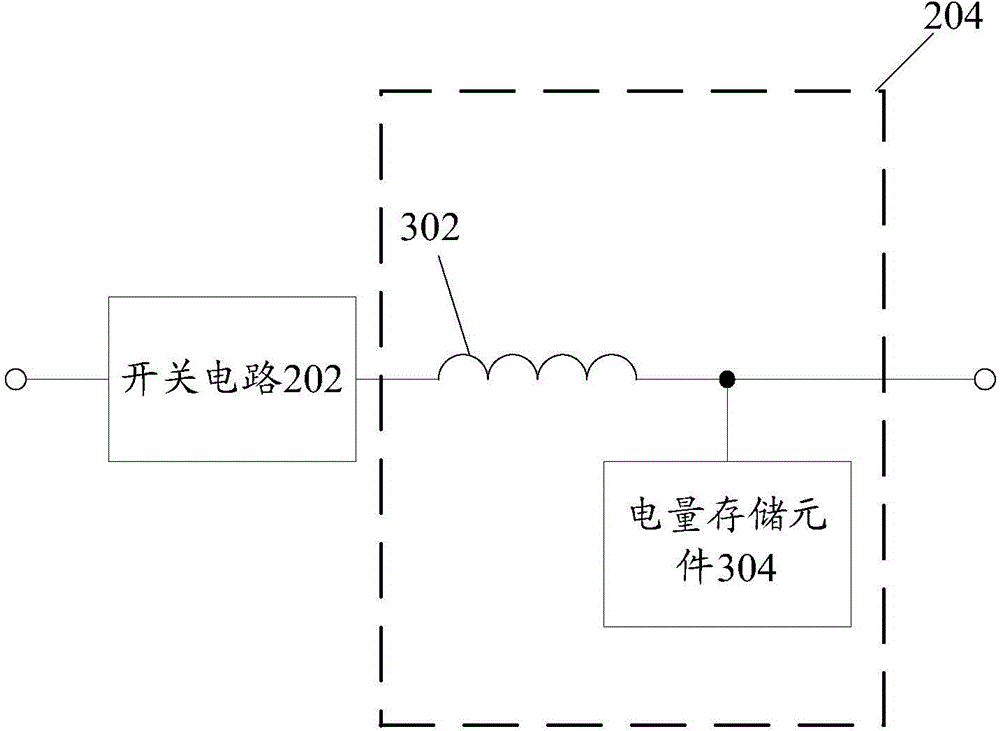
[0034] According to an embodiment of the present invention, an electric pressure cooker is provided, such as figure 2 As shown, the device includes:
[0035] The switch circuit 202 is used to open or close according to the input pulse signal;
[0036] The electromagnetic induction circuit 204 is connected with the switch circuit 202, and is used to generate an induced electromotive force according to the opening or closing of the switch circuit 202; wherein,
[0037] When the magnetic conduction device of the pressure vessel is close to the electromagnetic induction circuit 204, the induced electromotive force currently generated decreases, and the electromagnetic induction circuit 204 outputs a first voltage signal; when the magnetic conduction device is far away from the electromagnetic induction circuit At 204, the induced electromotive force currently generated increases, and the electromagnetic induction circuit 204 outputs a second voltage signal, wherein the first vol...
Embodiment 2
[0068] According to an embodiment of the present invention, there is also provided an electric pressure cooker, which includes:
[0069]A check valve, a permanent magnet arranged at the top of the check valve, and an electric pressure cooker with any of the above-mentioned features arranged above the permanent magnet.
[0070] In the electric pressure cooker provided by the embodiment of the present invention, the external single-chip microcomputer of the electric pressure cooker inputs a PWM signal to the electric pressure cooker to control the opening and closing of the first switching tube and the second switching tube, so that an induced electromotive force is generated between the inductor and the power storage element. The voltage at point a at time a is, for example, 4.5V. When the permanent magnet at the top of the check valve is close to the inductor, the magnetic flux passing through the inductor decreases, the induced electromotive force decreases, and the voltage a...
Embodiment 3
[0074] According to an embodiment of the present invention, there is also provided a method for detecting pressure on a pressure vessel, including:
[0075] Electric pressure cooker receives pulse signal to generate induced electromotive force;
[0076] When the magnetic conduction device is close to the electric pressure cooker, the induced electromotive force currently generated decreases, and the electric pressure cooker outputs a first voltage signal, wherein the first voltage signal indicates that the pressure vessel is in an upward pressure state; when the When the magnetic conduction device is away from the electric pressure cooker, the currently generated induced electromotive force increases, and the electric pressure cooker outputs a second voltage signal, wherein the second voltage signal indicates that the pressure vessel is in a no-pressure state.
[0077] In the pressure vessel detection method provided by the embodiment of the present invention, an external sing...
PUM
 Abstract
Description
Claims
Application Information
 - R&D
- Intellectual Property
- Life Sciences
- Materials
- Tech Scout
- Unparalleled Data Quality
- Higher Quality Content
- 60% Fewer Hallucinations
Browse by: Latest US Patents, China's latest patents, Technical Efficacy Thesaurus, Application Domain, Technology Topic, Popular Technical Reports.
© 2025 PatSnap. All rights reserved.Legal|Privacy policy|Modern Slavery Act Transparency Statement|Sitemap|About US| Contact US: help@patsnap.com


