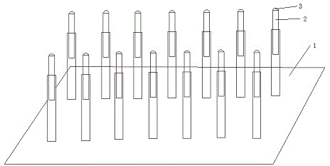
Test tube rack for preventing striking of test tube
A technology for test tube racks and test tubes, applied in the direction of test tube holders/clamps, etc., can solve the problems of broken test tube openings, excessive force, and test tube damage, and achieve good effect, simple structure, practical and convenient effects
- Summary
- Abstract
- Description
- Claims
- Application Information
AI Technical Summary
Problems solved by technology
Method used
Image
Examples
Embodiment 1
[0013] Such as figure 1 The shown test tube rack for preventing test tubes from being broken includes a base 1 and a fixed column 2 arranged on the base, and is characterized in that the fixed column 2 is two sections nested with each other, and the nested surfaces are rough surfaces , increase the friction, so that the upper half is not easy to slide down. When inserting test tubes of different lengths, the length of the fixed column 2 can be adjusted to make it longer than the test tube length. At this time, when the test tubes are inserted, the test tubes will not be bumped into the base 1, thereby avoiding damage.
Embodiment 2
[0015] Such as figure 1 The shown test tube rack for preventing test tubes from being broken includes a base 1 and a fixed column 2 arranged on the base, and is characterized in that the fixed column 2 is two sections nested with each other, and the nested surfaces are rough surfaces , increase the friction, so that the upper half is not easy to slide down. When inserting test tubes of different lengths, the length of the fixed column 2 can be adjusted to make it longer than the test tube length. At this time, when the test tubes are inserted, the test tubes will not be bumped into the base 1, thereby avoiding damage. The upper end of the fixed column 2 is provided with a sponge part 3, which relieves the force of the sleeve, and even if it is inserted quickly, the bottom of the test tube will not be damaged due to impact.
Embodiment 3
[0017] Such as figure 1 The shown test tube rack for preventing test tubes from being broken includes a base 1 and a fixed column 2 arranged on the base, and is characterized in that the fixed column 2 is two sections nested with each other, and the nested surfaces are rough surfaces , increase the friction, so that the upper half is not easy to slide down. When inserting test tubes of different lengths, the length of the fixed column 2 can be adjusted to make it longer than the test tube length. At this time, when the test tubes are inserted, the test tubes will not be bumped into the base 1, thereby avoiding damage. The upper end of the fixed column 2 is provided with a sponge part 3, which relieves the force of the sleeve, and even if it is inserted quickly, the bottom of the test tube will not be damaged due to impact. The sponge part 3 is hemispherical, which fits better with the bottom of the test tube, and prevents moisture deposition at the bottom of the test tube cau...
PUM
 Abstract
Description
Claims
Application Information
 - R&D
- Intellectual Property
- Life Sciences
- Materials
- Tech Scout
- Unparalleled Data Quality
- Higher Quality Content
- 60% Fewer Hallucinations
Browse by: Latest US Patents, China's latest patents, Technical Efficacy Thesaurus, Application Domain, Technology Topic, Popular Technical Reports.
© 2025 PatSnap. All rights reserved.Legal|Privacy policy|Modern Slavery Act Transparency Statement|Sitemap|About US| Contact US: help@patsnap.com

