
Optical fiber tapered grinder and grinding method thereof

A polisher and optical fiber technology, which is used in grinding devices, grinding machine tools, work carriers, etc., can solve the problems of inability to meet the needs of on-site grinding of optical fibers and complex structures.

Active Publication Date: 2017-12-22
SHENZHEN EPLU SCI TECH
View PDF7 Cites 0 Cited by
  • Summary
  • Abstract
  • Description
  • Claims
  • Application Information

AI Technical Summary

Problems solved by technology

Its disadvantage is that the structure is complex and cannot meet the needs of on-site grinding in the optical fiber construction process

Method used


Image

  • Optical fiber tapered grinder and grinding method thereof
  • Optical fiber tapered grinder and grinding method thereof
  • Optical fiber tapered grinder and grinding method thereof

Examples


Embodiment Construction

[0047] The present invention will be described in further detail below in conjunction with accompanying drawing:

[0048] Figure 1 to Figure 3 , Figure 7 to Figure 13 A first embodiment of the invention is shown.

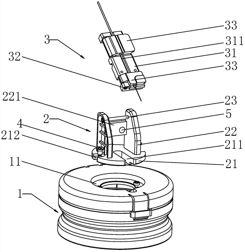
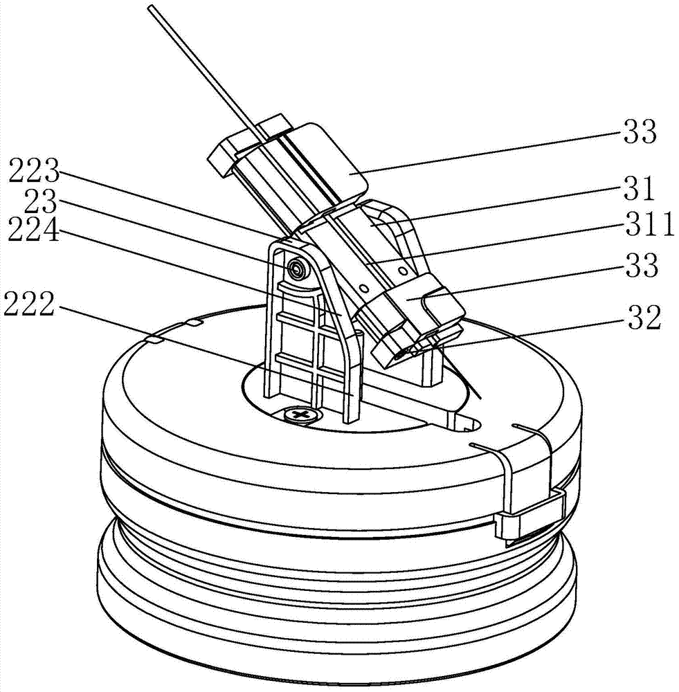
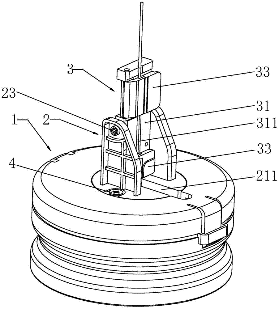
[0049] see figure 1 As shown, the optical fiber tapered grinder includes a grinder body 1, a base 2 and an optical fiber holder 3, the receiving port 11 on the top of the grinder body 3 is connected to the base 2 via a screw 4, and the pivot 23 on the top of the base 2 is detachable The fiber holder 3 is pivotally connected to the ground. The base 2 and the optical fiber holder 3 are connected to each other through joint members.

[0050] see Figure 1 to Figure 3 As shown, the base 2 is composed of the disc seat 21, the open groove 211 that runs through the edge of the disc seat 21 to the center of the circle, the screw holes 212 that are respectively recessed on the edge of the disc seat 21 perpendicular to the open groove 211, and the screw holes 212 that ...


PUM


Abstract

The invention relates to an optical fiber taper grinder and a grinding method thereof. A body containing port of the optical fiber taper grinder is connected with a base through screws, and a pivot of the base is pivoted to an optical fiber fixture in a detachable mode. When the optical fiber fixture is attached to the base to be in a work state, the length of a bare optical fiber is larger than the distance from the lower surface of the optical fiber fixture to a grinding sheet, an included angle is formed between the bare optical fiber and the grinding sheet, the bare optical fiber presses on the grinding sheet under the own elastic effect, and in the grinding process, the bare optical fiber is attached to the grinding sheet. The grinding method includes the steps that the optical fiber fixture with the optical fiber is obliquely placed on the pivot of the base to be pressed to the vertical direction with the pivot as a center, an inclination angle is formed between the optical fiber and the grinding sheet, and the optical fiber fixture is vertically fixed by the use of the base and the magnet of the optical fiber fixture; a rotating mechanism of the grinder is rotated, taper rotation is conducted with the clamped point of the bare optical fiber as a circle center, and the end face of the bare optical fiber changes from a plane to a taper plane after being ground; after the grinding is completed, with the pivot as a center, the optical fiber fixture is rotated reversely, and the optical fiber fixture is taken down.

Description

technical field [0001] The invention relates to the technical field of optical fiber communication, in particular to an optical fiber tapered grinder and a grinding method thereof. Background technique [0002] CN201480001086.8 discloses an optical fiber end face grinder, and its purpose is to propose a fiber end face grinder with simple structure, small volume and portability. The technical solution: an optical fiber end face grinder, including a housing, the top of the housing is provided with an optical fiber fixing module, the bottom of the housing is provided with a base that can rotate relative to the housing, the base is provided with an eccentric connecting portion, and the connecting portion is connected with a The transmission shaft that revolves with the rotation of the base, the transmission shaft sleeve is provided with a pinion gear with annular external meshing teeth, and the inner side of the casing is provided with a large gear with annular internal meshing ...

Claims


Application Information

Patent Timeline
Patent Type & Authority Patents(China)
IPC IPC(8): B24B37/00B24B37/27
CPCB24B37/00B24B37/27
Inventor 杨国秦江波王七月周震
Owner SHENZHEN EPLU SCI TECH
Learn More