Resin forming device and resin forming method

A resin molding and resin technology, which is applied in the field of resin molding equipment and resin molding to achieve the effect of stable supply

Active Publication Date: 2015-09-30
TOWA
View PDF5 Cites 7 Cited by
  • Summary
  • Abstract
  • Description
  • Claims
  • Application Information

AI Technical Summary

Problems solved by technology

However, this structure has the problem that the operating gas B cannot sufficiently contact the residual material 43 from the output port 23b of the second nozzle 23.

Method used


Image

  • Resin forming device and resin forming method
  • Resin forming device and resin forming method
  • Resin forming device and resin forming method

Examples


Embodiment 1

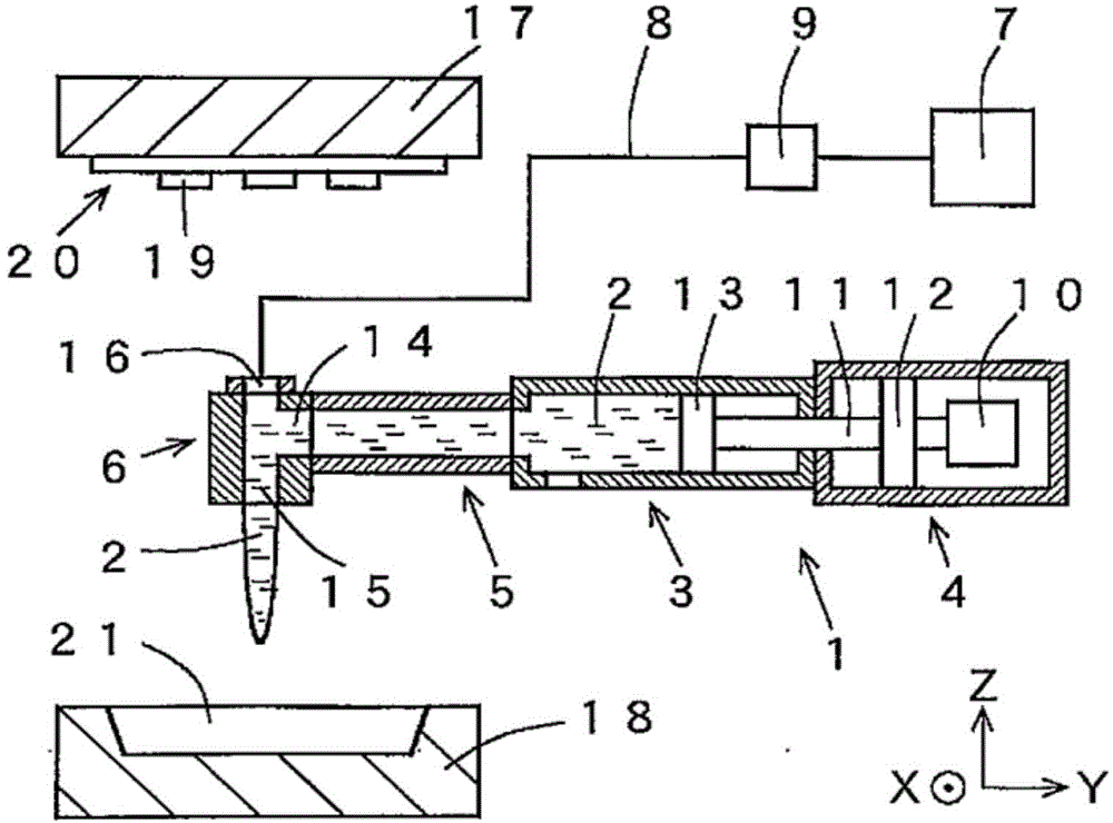
[0090] Embodiment 1 of the resin supply mechanism of the resin molding apparatus of the present invention will be described with reference to FIGS. 1( a ) to ( b ) and FIGS. 2( a ) to ( d ). For ease of understanding, any of the drawings in this application are appropriately omitted or exaggerated and then schematically drawn. The same symbols are assigned to the same constituent elements, and explanations thereof are appropriately omitted.

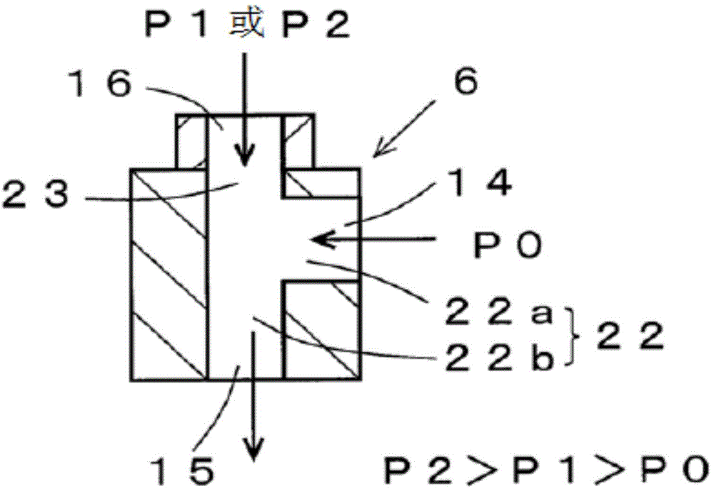
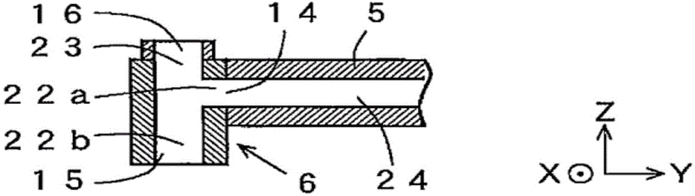
[0091] The dispenser 1 which is the resin supply mechanism shown in FIG. 1( a ) is a horizontal dispenser arranged in the horizontal direction. The dispenser 1 includes: a storage unit 3 for storing the liquid resin 2; a metering and delivery mechanism 4 for measuring and delivering a specific amount of the liquid resin 2; a resin transfer unit 5 for transferring the delivered liquid resin 2; and a nozzle 6 for It is a discharge part which discharges the transferred liquid resin 2.

[0092] The compressor 7 is a pressurizing mechanism t...

Embodiment 2

[0112] Embodiment 2 of the resin supply mechanism of the resin molding apparatus of the present invention will be described with reference to FIGS. 3( a ) to ( b ). The difference from Example 1 is that in the nozzle 6, the air supply port is provided not only on the top surface of the nozzle 6 but also on the side surface. As shown in FIG. 3( a ), for example, in addition to the main air supply port 16 , auxiliary air supply ports 28 a , 28 b , and 28 c can also be provided on the side surfaces of the nozzle 6 . The air supply ports 28a, 28b, and 28c are connected to the resin passage 22b via air passages 29a, 29b, and 29c, respectively. A plurality of air supply ports can be provided on the side surface of the nozzle 6 as needed.

[0113] In FIG.3(b), for example, the air passage 29b is provided along the horizontal direction (+Y direction) from the air supply port 28b. With pressure P3(kg / cm 2 ), the compressed air 30 is sprayed from the air supply port 29b to the resin ...

Embodiment 3

[0116]Embodiment 3 of the resin supply mechanism of the resin molding apparatus of the present invention will be described with reference to FIGS. 4( a ) to ( b ). The difference from Example 1 is that first, the metering and delivery mechanism 4 , the storage unit 3 and the resin transfer unit 5 are arranged along the vertical direction. Second, between the resin transfer part 5 and the nozzle 6, the resin direction changing member 31 which changes the flow direction of the liquid resin 2 is provided. As shown in FIG. 4( a ), the resin direction changing member 31 includes a resin supply port 32 and a resin delivery port 33 . The resin passage 34 connecting the resin supply port 32 and the resin delivery port 33 includes: a resin passage 34a extending from the resin supply port 32 in the vertical direction (-Z direction); and a resin passage 34b extending from the resin passage 34a along the Extends in the horizontal direction (-Y direction). Therefore, the resin supply por...


PUM


Abstract

The invention provides a resin forming device and a resin forming method. In the resin forming device, liquid resin is ejected out through supplying compressed air to a nozzle. A nozzle (6) mounted on the front end of a distributor (1) is provided with a resin supply port (14), a resin ejecting port (15) and an air supply port (16). The resin feed port (14) is connected with the resin ejecting port (15) through a resin channel (22a) extending along the horizontal direction and a resin channel (22b) vertically extending perpendicular to the resin channel (22a). Compressed air in a compressor (7) is supplied to the air supply port (16) through pressure P1 lager than resin pushing pressure P0, to prevent liquid resin (2) from entering into the air supply port (16). The compressed air is ejected to the liquid resin (2) stored in the resin channel (22b) through pressure P2 larger than P1, and the residual liquid resin (2) in the resin channel (22b) can be extruded from the resin ejecting port, so that a certain amount of liquid resin (2) can be supplied to a die cavity (21).

Description

technical field [0001] The present invention relates to a resin molding device and a resin molding method for using a liquid resin to oppose transistors, integrated circuits (Integrated Circuit: IC), light emitting diodes (Light Emitting Diode: LED ) and other wafer-shaped electronic components (hereinafter appropriately referred to as "wafer") are resin-sealed. In the present application, the term "liquid" means that it is liquid at normal temperature and has fluidity, regardless of the level of fluidity, in other words, regardless of the degree of viscosity. Background technique [0002] Conventionally, wafers of optical elements such as LEDs mounted on substrates have been resin-sealed with sealing resins containing cured resins using thermosetting and light-transmitting liquid resins such as silicone resins and epoxy resins. As a technique for resin sealing, resin molding techniques such as compression molding and transfer molding are used. In the resin molding process...

Claims


Application Information

Patent Timeline
IPC IPC(8): B29C70/36B29C70/54
CPCB29C70/36B29C70/54
Inventor 山田哲也后藤智行岩田康弘花坂周邦
Owner TOWA
Why Eureka
Try Eureka