
Walking moon soft landing mechanism

A moon and lander technology, applied in the aerospace field, can solve problems such as insufficient maneuverability, lack of active attitude adjustment, and inability of the lander to actively control and adjust, so as to achieve the effect of preventing overturning and stabilizing the landing process

Inactive Publication Date: 2015-09-30
SHANGHAI AEROSPACE SYST ENG INST
View PDF7 Cites 35 Cited by
  • Summary
  • Abstract
  • Description
  • Claims
  • Application Information

AI Technical Summary

Problems solved by technology

At present, the known soft landing mechanism can only achieve soft landing. After landing, the lander can only be fixed at the landing point, and then detect the vicinity of the landing area by moving vehicles or other means. When the detection means are insufficient, it will not be possible to carry out detection Task
In addition, the usual soft landing mechanism can only maintain a buffered state after landing, and does not have the ability to actively adjust the attitude. , the lander will appear in a non-level state such as attitude tilt and cannot be actively controlled and adjusted, which may also affect the implementation of subsequent detection tasks
[0004] To sum up, the currently known soft landing mechanisms for landers are not maneuverable enough to effectively move the lander in the landing area, and most soft landing mechanisms only solve the problem of stable landing, but do not consider the attitude adjustment of the whole device after landing. Therefore, the ability to adapt to complex detection environments and detection task requirements is not good

Method used


Image

  • Walking moon soft landing mechanism
  • Walking moon soft landing mechanism
  • Walking moon soft landing mechanism

Examples


Embodiment Construction

[0021] The technical solutions in the embodiments of the present invention will be clearly and completely described and discussed below in conjunction with the accompanying drawings of the present invention. Obviously, what is described here is only a part of the examples of the present invention, not all examples. Based on the present invention All other embodiments obtained by persons of ordinary skill in the art without creative efforts fall within the protection scope of the present invention.

[0022] In order to facilitate the understanding of the embodiments of the present invention, specific embodiments will be taken as examples for further explanation below in conjunction with the accompanying drawings, and each embodiment does not constitute a limitation to the embodiments of the present invention.

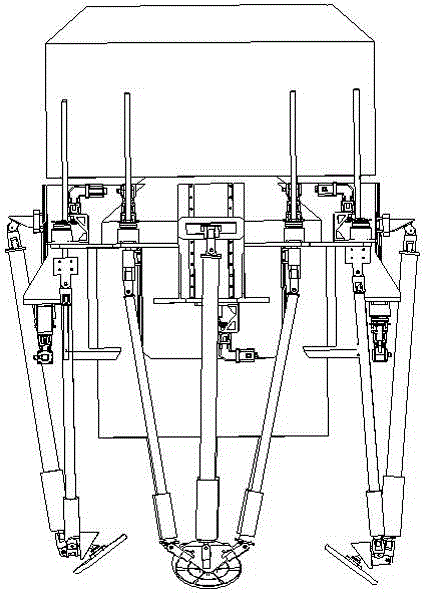
[0023] Such as figure 1 As shown, the walkable lunar soft landing mechanism provided by the present invention consists of four landing buffer legs 1 evenly installed on ...


PUM


Abstract

The invention discloses a walking moon soft landing mechanism. The walking moon soft landing mechanism comprises a plurality of landing buffering legs evenly installed on the side wall of a landing device. Each landing buffering leg comprises a main buffering supporting column assembly, two auxiliary buffering supporting column assemblies symmetrically installed on the two sides of the main buffering supporting column assembly, a foot pad and a connecting plate. Each main buffering supporting column assembly and each auxiliary buffering supporting column assembly each comprise a buffering supporting column, a sliding block, a sliding rail, a lead screw and a driving transmission part. Buffering materials are installed inside each buffering supporting column, and each buffering supporting column is used for being compressed and stretched in a bidirectional mode. Each sliding block is hinged to the upper end of the corresponding buffering supporting column. Each sliding rail is fixed to the side wall of the landing device. Each sliding block is connected to the corresponding sliding rail in a slideable mode. One end of each lead screw is connected with the corresponding sliding block. Each driving transmission part is connected with the other end of the corresponding lead screw. Each sliding block is driven by the corresponding lead screw to move on the corresponding sliding rail to unfold or fold the corresponding landing buffering leg. The lower end of the buffering supporting column of each main buffering supporting column assembly and the lower ends of the buffering supporting columns of the corresponding auxiliary buffering supporting column assemblies are jointly hinged to the corresponding connecting plate. Each connecting plate is connected with the corresponding foot pad through a spherical hinge.

Description

technical field [0001] The invention relates to the field of aerospace technology, in particular to a soft landing mechanism that enables a lander to have a walking function. Background technique [0002] In the landing detection of the lander, in addition to the soft landing that the lander can achieve, with the requirements of the detection mission and the special requirements for the working attitude of the lander from some payloads, the movement ability and attitude of the lander after landing There is also an increasing need to adjust capabilities to meet the needs of detection missions. [0003] The soft landing mechanism is used in the field of lander attachment detection to realize energy buffering and absorption when the lander lands, and to ensure that the lander is stably and reliably attached to the ground. At present, the known soft landing mechanism can only achieve soft landing. After landing, the lander can only be fixed at the landing point, and then dete...

Claims


Application Information

Patent Timeline
IPC IPC(8): B64G1/16
Inventor 刘志周杰靳宗向刘永强胡雪平樊继壮
Owner SHANGHAI AEROSPACE SYST ENG INST
Learn More