Arc-shaped plate fixed-distance conveying method for ampoules

A curved plate and ampoule technology, which is applied in the field of conveying, can solve the problems of ampoule damage and ampoule fixed-distance transmission mechanism damage, and achieves the effect of preventing breakage, simple structure and protecting the ampoule.

Inactive Publication Date: 2015-09-30
CHINA CHENGDU ANIMAL HUSBANDRY IND BIOPHARM
View PDF0 Cites 0 Cited by
  • Summary
  • Abstract
  • Description
  • Claims
  • Application Information

AI Technical Summary

Problems solved by technology

[0005] The purpose of the present invention is to solve the problem that the ampoule is often damaged or the ampoule fixed-distance transmission mechanism is damaged at the connection between the existing ampoule release mechanism and the ampoule fixed-distance transmission mechanism, and to provide an arc for ampoule that solves the above problems. Shape plate fixed distance transmission method

Method used


Image

  • Arc-shaped plate fixed-distance conveying method for ampoules
  • Arc-shaped plate fixed-distance conveying method for ampoules

Examples


Embodiment 1

[0026] The fixed-distance conveying method of an ampoule with a curved plate comprises the following steps:

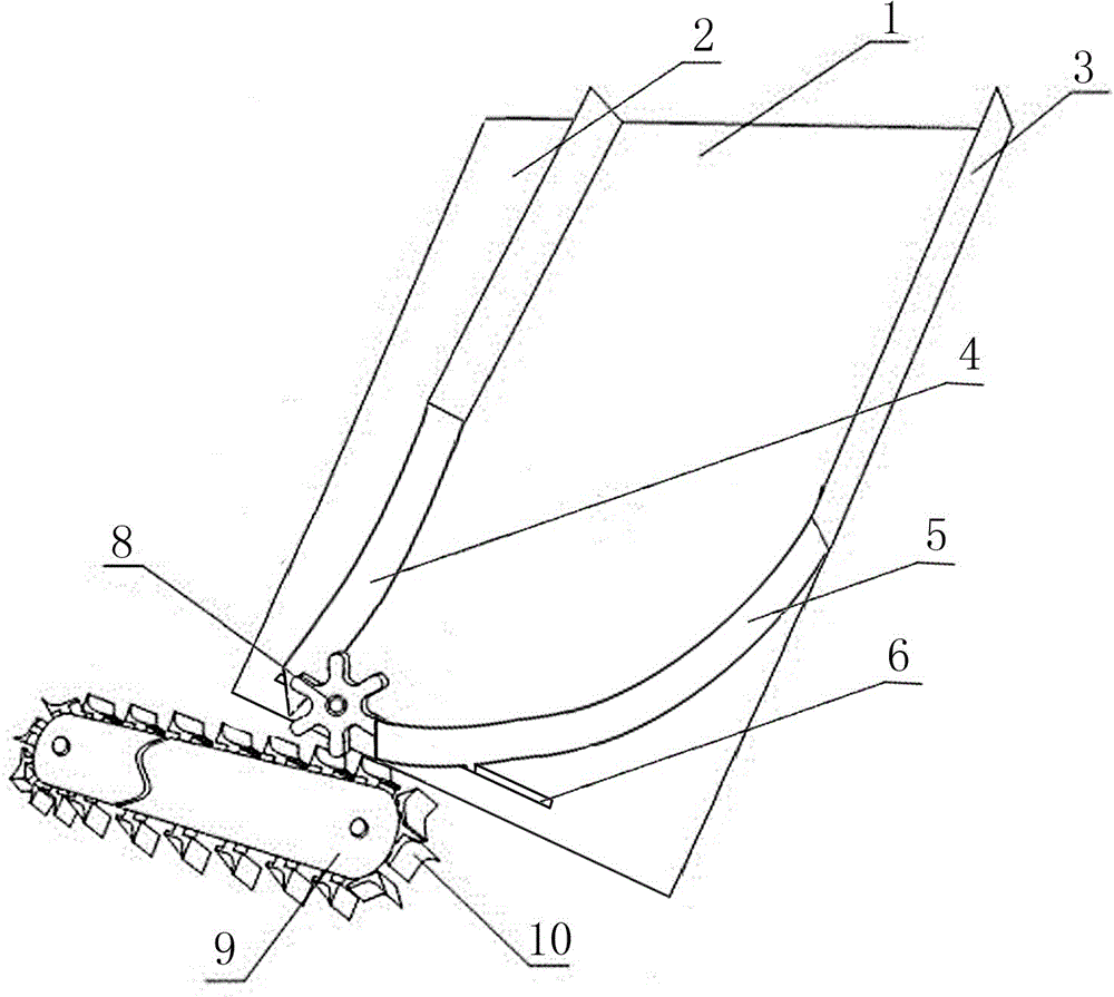
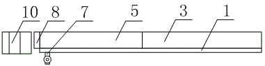
[0027] (1) Adjust the distance between the first arc-shaped protection plate and the second arc-shaped protection plate on the bottom plate of the trough according to the size of the conveying ampoule, and use the bolts and nuts below the bottom plate of the chute to protect the first arc-shaped protection plate. The positions of the plate and the second arc protection plate are fixed;

[0028] (2) Put the ampoule on the bottom plate of the trough, and the ampoule is transported to the conveyor belt through the guide channel formed by the first arc-shaped protective plate and the second arc-shaped protective plate, and the transport is limited by the ampoule block on the conveyor belt. The distance between the bottles, and finally the ampoule with a limited distance can be transmitted.

[0029] In the present invention, the structure of the arc-shaped plate fixed-dist...

Embodiment 2

[0035] The difference between this embodiment and Embodiment 1 is that between the ampoule release mechanism and the ampoule fixed-distance transmission mechanism, an ampoule guide wheel 8 is added at the position of the ampoule release mechanism, and the specific settings are as follows:

[0036] The guide passage outlet is also provided with an ampoule guide wheel 8, which is made up of a gear-shaped runner located at the guide passage outlet, and a motor that drives the runner to rotate.

Embodiment 3

[0038] The difference between this embodiment and Embodiment 2 is that the structure of the ampoule fixed-distance transmission mechanism is optimized, and the specific setting method is as follows:

[0039] The ampoule block 10 is strip-shaped, and its length direction is parallel to the width direction of the conveyor belt 9. The bottom end of the ampoule block 10 is fixedly connected to the conveyor belt 9, and an arc-shaped surface is arranged on the upper part of the ampoule block 10. , the arc-shaped surface is tangent to one side of the ampoule block 10 , and the arc-shaped surface intersects the other side of the ampoule block 10 .


PUM


Abstract

The invention discloses an arc-shaped plate fixed-distance conveying method for ampoules. By the adoption of an arc-shaped plate fixed-distance conveying device for ampoules, fixed-distance conveyance of ampoules is achieved. The method comprises the steps of 1, adjusting the distance between a first arc-shaped protective plate and a second arc-shaped protective plate on a trough base plate according to the size of the ampoules to be conveyed, and fixing the first arc-shaped protective plate and the second arc-shaped protective plate through bolts and nuts below the trough base plate; 2, placing the ampoules on the trough base plate, conveying the ampoules to a conveyer belt through a guiding channel formed by the first arc-shaped protective plate and the second arc-shaped protective plate, limiting the distance between the conveyed ampoules through ampoule clamping blocks on the conveyer belt, and finally conveying the ampoules with distance well limited out. The method is suitable for conveying ampoules in different specifications and sizes and has the advantages that the ampoules can be well protected and ampoule conveyance efficiency is not affected.

Description

technical field [0001] The invention relates to a conveying method, in particular to a fixed-distance conveying method using arc-shaped plates for ampoules. Background technique [0002] The cleaning, filling and packaging of ampoules in pharmaceutical companies all require the use of ampoules conveyor belts. In the above-mentioned cleaning and packaging process, in order to make the surface of the ampoules fully contact with the cleaning solution, or during the sealing and labeling process of the package, Avoid adjacent ampoules being close to each other and affecting the effect of adding caps on ampoules, heating ampoules, glass heat sealing or labeling. The conveyor belt used for the above cleaning and packaging processes needs to carry out fixed-distance transmission for ampoules. [0003] In the prior art, the ampoule conveyor belt used in the above process mostly adopts the transmission mode of intermittent transmission or a special distance-fixed mechanism, such as a ...

Claims


Application Information

Patent Timeline
Patent Type & Authority Applications(China)
IPC IPC(8): B65G47/57B65G17/12B65G17/32
Inventor 廖成斌卢朝成
Owner CHINA CHENGDU ANIMAL HUSBANDRY IND BIOPHARM
Why Eureka
Try Eureka