Ceramic ball valve

A technology for ceramic ball valves and valve seats, which is applied to valve details, valve devices, shaft seals, etc. It can solve problems such as difficulty in rotation, leakage of valve seats and middle bodies, and inability to automatically compensate for wear of valve seats and valve balls to achieve wear compensation. , Improve the effect of sealing

Inactive Publication Date: 2015-09-30
王林振
View PDF10 Cites 3 Cited by
  • Summary
  • Abstract
  • Description
  • Claims
  • Application Information

AI Technical Summary

Problems solved by technology

Disadvantages: 1. The unilateral disc spring compensates the wear of the valve seat and the valve core, which easily causes the valve core to shift to one side, causing the valve core and the valve stem to be out of axis, making it difficult to rotate, and breaking the valve core
2 The valve seat on the left is sealed with the middle body and the valve core, forming an over-positioning, which may easily cause leakage between the valve seat and the middle body, and cause the medium to corrode the shell
Disadvantages: 1. When the valve seat and the valve ball are worn, the valve seat and the valve ball will leak, and the wear of the valve seat and the valve ball cannot be automatically compensated
2. When the whole valve is installed in the pipeline, the pipeline flange will squeeze the valve seat of the valve, causing the two valve seats to move in the middle and hold the valve ball tightly, which is easy to lock the valve ball

Method used


Image

  • Ceramic ball valve

Examples


Embodiment Construction

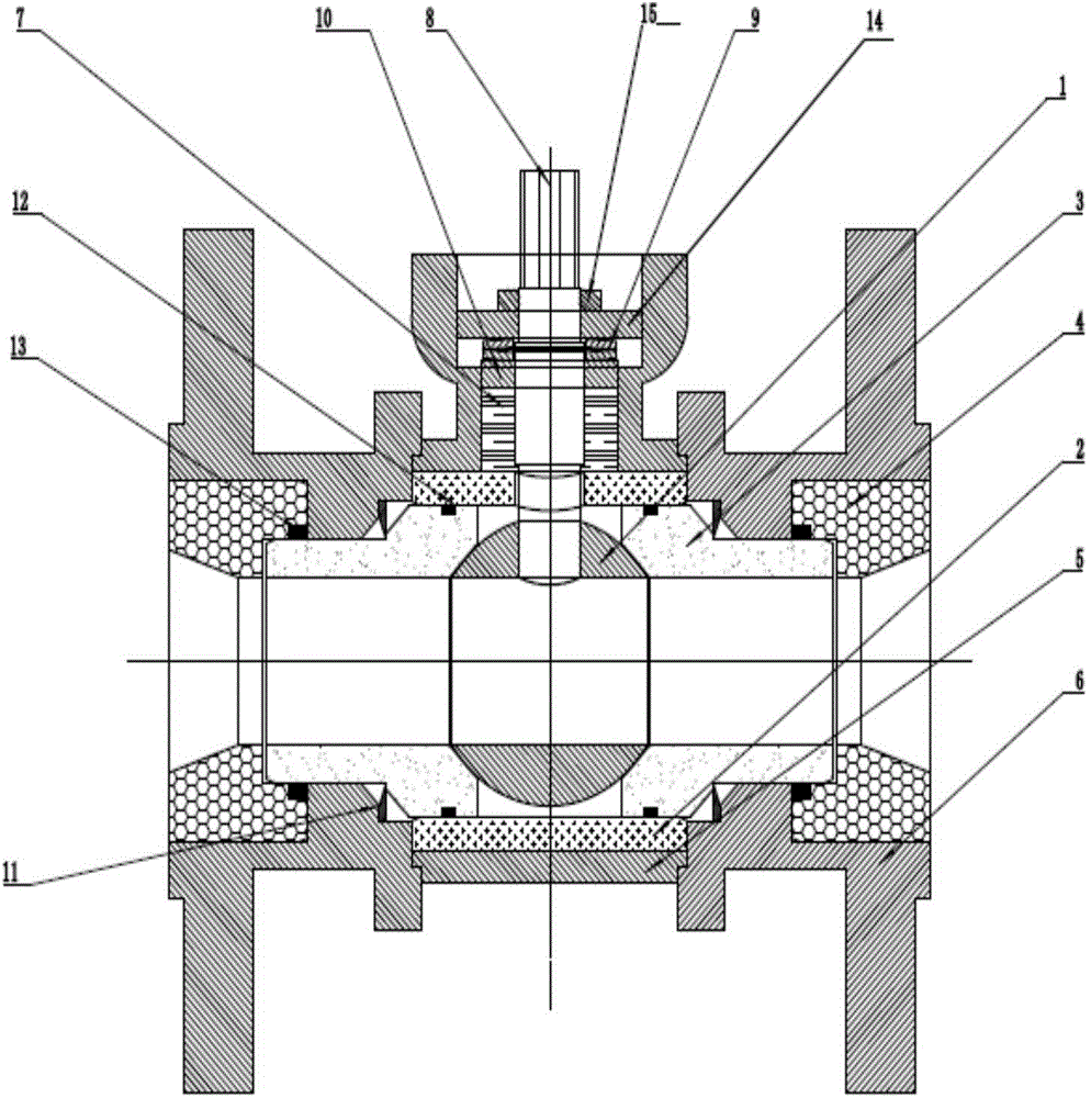
[0015] The present invention will be described in detail below in conjunction with specific embodiments and accompanying drawings.

[0016] As shown in the accompanying drawings, a ceramic ball valve of the present invention includes a valve seat 3 installed in the middle body 2, and there is a flow passage for fluid in the valve seat 3, and the valve seat is installed in the valve seat. There is a spool 1, the transverse through hole of the spool 1 and the flow channel of the valve seat can be in two states of through and closed, flanges 6 are respectively installed on both sides of the outer middle body of the valve seat 3, A valve stem 8 is connected to the valve core through a hole in the middle body, the valve stem is installed in the housing 5, and flange liners 4 are inlaid in the flanges outside the valve seat 3 respectively. A groove step is provided on the valve seat 3 near the junction of the valve seat on the two outer sides of the middle body and the inner side of...


PUM


Abstract

The invention discloses a ceramic ball valve. The ceramic ball valve comprises a valve seat mounted in a midbody; a runner allowing a fluid to pass is arranged in the valve seat; a valve core is mounted in the valve seat; a flange is mounted on each of two sides of the midbody outside the valve seat; a valve rod is connected with the valve core through a hole in the midbody and mounted in a housing; a flange inner lining is embedded into each of the flange on the outer side of the valve seat; bevel steps are arranged on the valve seat, close to the two outer sides of the midbody, and the valve seat, at the inner-side junctions of the flanges; cushioning springs are mounted between the valve seat at the bevel steps and the flanges; steps are formed at the contact parts of the flanges and the inner end parts of the flange inner linings; the inner end parts of the flange inner linings and the flanges are in compressed contact at the steps of the flanges; between the valve rod and the housing, a sealing filler, a compression ring, a disc spring, a pressure plate and a limiting ring are sequentially arranged from the outer side of the midbody to the outside; and the pressure plate is fixed on a platform in the housing through a bolt. By adoption of the structure, the valve seat can be automatically repaired under the action of the disc spring after being abraded.

Description

technical field [0001] The invention relates to a ceramic valve, in particular to a ceramic ball valve. Background technique [0002] The Chinese patent No. CN201110222440.8 discloses "a ceramic ball valve", which is composed of a shell, a valve stem, a ceramic ball, a left ceramic valve seat, a right ceramic valve seat, a ceramic middle body, and a ceramic flange lining. The outer surface of the left ceramic valve seat is in close contact with the inner surface of the shell, the outer surface of the right ceramic valve seat is in close contact with the inner surface of the ceramic middle body, and the other end of the ceramic middle body is in close contact with the left The inside of the ceramic valve seat is in close contact. A disc spring compression ring is installed between the right elevation of the right ceramic valve seat and the inner lining of the ceramic flange, and a disc spring is installed between the disc spring compression ring and the right elevation of the...

Claims


Application Information

Patent Timeline
Patent Type & Authority Applications(China)
IPC IPC(8): F16K5/20F16K41/02
CPCF16K5/0694F16K5/201
Inventor 王林振
Owner 王林振
Why Eureka
Try Eureka