centrifugal magnetic drive

A magnetic transmission and centrifugal technology, applied in the transmission device, the device for adjusting the transmission torque, can solve the problems of unstable transmission torque, short service life of the equipment, large size of the magnetic transmission device, etc., and achieve axial installation. The distance is short, the structure is simple and compact, and the effect of saving magnetic material resources

Active Publication Date: 2017-05-31
良明(天津)科技有限公司
View PDF5 Cites 1 Cited by
  • Summary
  • Abstract
  • Description
  • Claims
  • Application Information

AI Technical Summary

Problems solved by technology

When the general permanent magnet coupling performs torque transmission, since the permanent magnet rotor and the conductor rotor have been fixed in advance, at the moment of starting, due to the large speed difference between the input and output shafts and the relatively constant magnetic field strength, the conductor rotor The instantaneous eddy current generated is very large, and the heat is serious. The high-power coupling even needs auxiliary cooling equipment such as water cooling, and the service life of the equipment is relatively low.
Even if the distance between the permanent magnet rotor and the conductor rotor is adjustable, it must be completed by a special actuator and controller, the mechanism is complex, the process requirements are high, and the service life of the equipment is short.
Moreover, the magnetic transmission device is large in size, difficult to adjust the dynamic balance, and the generated transmission torque is unstable, causing the output shaft to vibrate, causing damage to the equipment, and even causing major losses to production and life.
[0003] At present, permanent magnets are generally used in transmission devices using magnets, and the magnetic field strength is fixed and cannot be adjusted with changes in speed and torque.
For example, the Chinese invention patent application with publication number CN103023272A discloses a permanent magnet to realize an eddy current flexible transmission coupling. Although the force radius of the magnet changes, the magnetic field strength does not change, and the magnetic field is very strong during the initial transmission. The radius of action is small, and the torque is not enough to drive the load to rotate quickly, so it will work in this state for a long time, causing a lot of heat, demagnetizing the permanent magnet, and there is a weakness in the transmission torque reduction. It also determines the two poles because of its structure. The farther away the magnetic circuit is, the magnetic force is naturally weakened, the instantaneous eddy current generated in the conductor rotor is reduced, and the effect is also reduced. There are shortcomings and deficiencies in the transmission torque of the same volume. Therefore, the diameter of the rotor must be increased and the volume of the magnet must be larger. The magnetic pole spacing is also relatively large, the magnetic circuit stroke is long, and there are shortcomings and deficiencies in the natural weakening of the magnetic force, which is easy to cause waste of space and materials
Especially when running at high speed, the centrifugal force will be greater, causing potential damage factors, and it will also cause the conductor ring in the driven part to generate a large amount of heat instantly, resulting in demagnetization and scrapping

Method used


Image

  • centrifugal magnetic drive
  • centrifugal magnetic drive
  • centrifugal magnetic drive

Examples


Embodiment 1

[0038] Embodiment 1 single-sided transmission mode

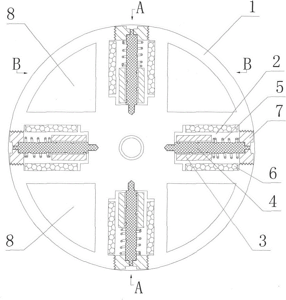
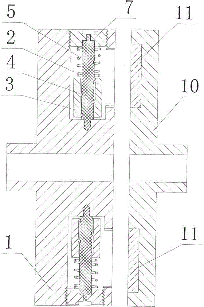
[0039] see figure 1 , 2 , 3, 4, 5 and 10 for the structures represented.

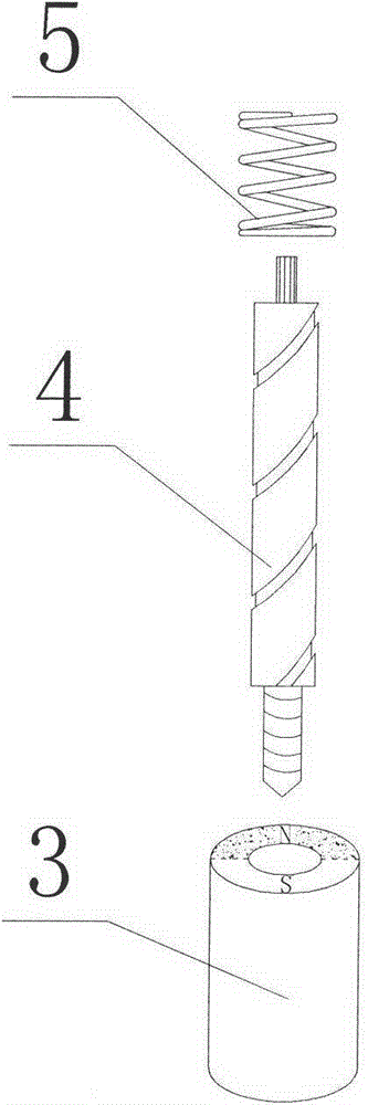
[0040] A centrifugal magnetic transmission device, comprising a driving rotor 1 for connecting an input shaft, a driven rotor 10 for connecting an output shaft, the driving rotor figure 1 There are a number of cavities 2 opened in the radial direction. These cavities 2 are evenly distributed around the axis of the driving rotor. The magnetic drive mechanism components are arranged in the cavities 2. The driven rotor 10 is provided with a conductor ring 11. The material of the conductor ring is selected Metals that conduct electricity well, such as copper or aluminum. see image 3 , wherein the magnetic drive mechanism assembly includes: a magnet 3, a helical spool 4 and a magnet return spring 5, one end of the helical spool 4 placed in the cavity 2 is fixedly connected with the drive rotor 1 in a threaded manner, and the other end of the helical s...

Embodiment 2

[0045] Embodiment 2 double-sided transmission mode

[0046] see figure 1 , 6 and the structure represented in 7.

[0047] On the basis of the basic structure of Embodiment 1, furthermore, a double conductor ring 11 is provided in the driven rotor 10, that is, the driven rotor 10 adopts a cage structure surrounding the driving rotor 1, inside the driven rotor 10, and Conductor rings are arranged on both sides close to the driving rotor 1; Image 6 , and the magnetic poles 6 are open in both directions, which can make the conductor rings on both sides of the driven rotor 10 generate eddy current resistance, which is about twice the torque of the first embodiment, and achieves the purpose of non-contact flexible transmission. The structure of the device Simple, small in size and large in torque, it can generally be used in transmission equipment with medium torque.

Embodiment 3 3

[0048] Embodiment 3 three-sided transmission mode

[0049] see figure 1 , 7 and the structures represented in 8.

[0050] On the basis of Embodiment 2, in order to make full use of the magnetic field of the magnet 3, this embodiment is aimed at the magnetic field along the radial direction of the driving rotor and the outer end surface of the magnet 3. Further, in the driven rotor 10, except for the double-sided conductor ring 11, In the driven rotor, there is also a conductor ring on the side corresponding to the outer end face of the magnet 3, that is, an outer circular conductor ring 12; see Figure 9 , the inside of the magnet 3 is provided with a housing chamber 9 for a magnet return spring; the rotor 1 is driven to rotate, and during the sliding process of the magnet 3 under centrifugal force, the magnet return spring 5 is squeezed and accommodated in the housing chamber 9; so that the outer end of the magnet 3 The distance from the outer circular conductor ring 12 ca...


PUM


Abstract

The invention discloses a centrifugal magnetic transmission device which comprises a driving rotor and a driven rotor. A conductor loop is arranged inside the driven rotor. Magnetic force driving mechanisms are arranged in cavities which are formed in the radial direction of the driving rotor. Each magnetic force driving mechanism comprises a magnet, a spiral thread reel and a magnet reset spring, each magnet can rotate around one corresponding spiral thread reel along a track and slide along the spiral thread reel, and torque can be adjusted in the rotating and sliding processes of the magnets. In a non-operating state, N poles and S poles of the magnets are arranged in the axial direction, when the magnets are rotated by 90 degrees or 270 degrees, an eddy generated in the conductor loop of the driven rotor is maximum, the transmitted torque is maximum, especially when a three-face conductor loop structure is adopted, the magnetic field is fully utilized, and under the condition of the same torque and the same weight, the transmission effect is improved by several times. According to the centrifugal magnetic transmission device, electrical control devices are needless, the torque is adjusted automatically, adjustable soft starting is achieved automatically, the advantages of being small in size, large in torque, little in heating, simple in structure, orderly in appearance and compact in structure are achieved, and the service life of the device is long.

Description

technical field [0001] The invention relates to a transmission device, in particular to a device with a magnet drive assembly, in particular to a device for adjusting the size of the transmitted torque through the rotation and radial distance of the magnet. It belongs to the technical field of electromechanical manufacturing. Background technique [0002] Due to its simple structure, shock absorption and noise reduction, non-contact transmission and other advantages, the magnetic transmission device has been more and more widely selected by industrial enterprises in recent years. Drive coupling equipment is used in almost all production and living power drag equipment. When the general permanent magnet coupling performs torque transmission, since the permanent magnet rotor and the conductor rotor have been fixed in advance, at the moment of starting, due to the large speed difference between the input and output shafts and the relatively constant magnetic field strength, th...

Claims


Application Information

Patent Timeline
Patent Type & Authority Patents(China)
IPC IPC(8): H02K51/00
Inventor 佟宪良
Owner 良明(天津)科技有限公司
Why Eureka
Try Eureka