Eureka AIR delivers breakthrough ideas for toughest innovation challenges, trusted by R&D personnel around the world.

Power grid deicing device

A technology of power grid and driving device, which is applied in the installation of cables, overhead installation, electrical components, etc., which can solve the problems of danger, icicle obstacles, and motor heating, etc. Effect

Active Publication Date: 2020-07-17
株洲锐利切削工具股份有限公司
View PDF7 Cites 0 Cited by
  • Summary
  • Abstract
  • Description
  • Claims
  • Application Information

AI Technical Summary

Problems solved by technology

[0003] In view of the above situation, in order to solve the problems existing in the prior art, the purpose of the present invention is to provide a power grid deicing device, which solves the problem of icicle obstacles encountered in the prior art, and when it cannot move forward smoothly, the motor will generate heat, which will easily cause dangerous question

Method used


Image

  • Power grid deicing device
  • Power grid deicing device
  • Power grid deicing device

Examples


Embodiment Construction

[0015] The specific implementation manners of the present invention will be described in further detail below in conjunction with the accompanying drawings.

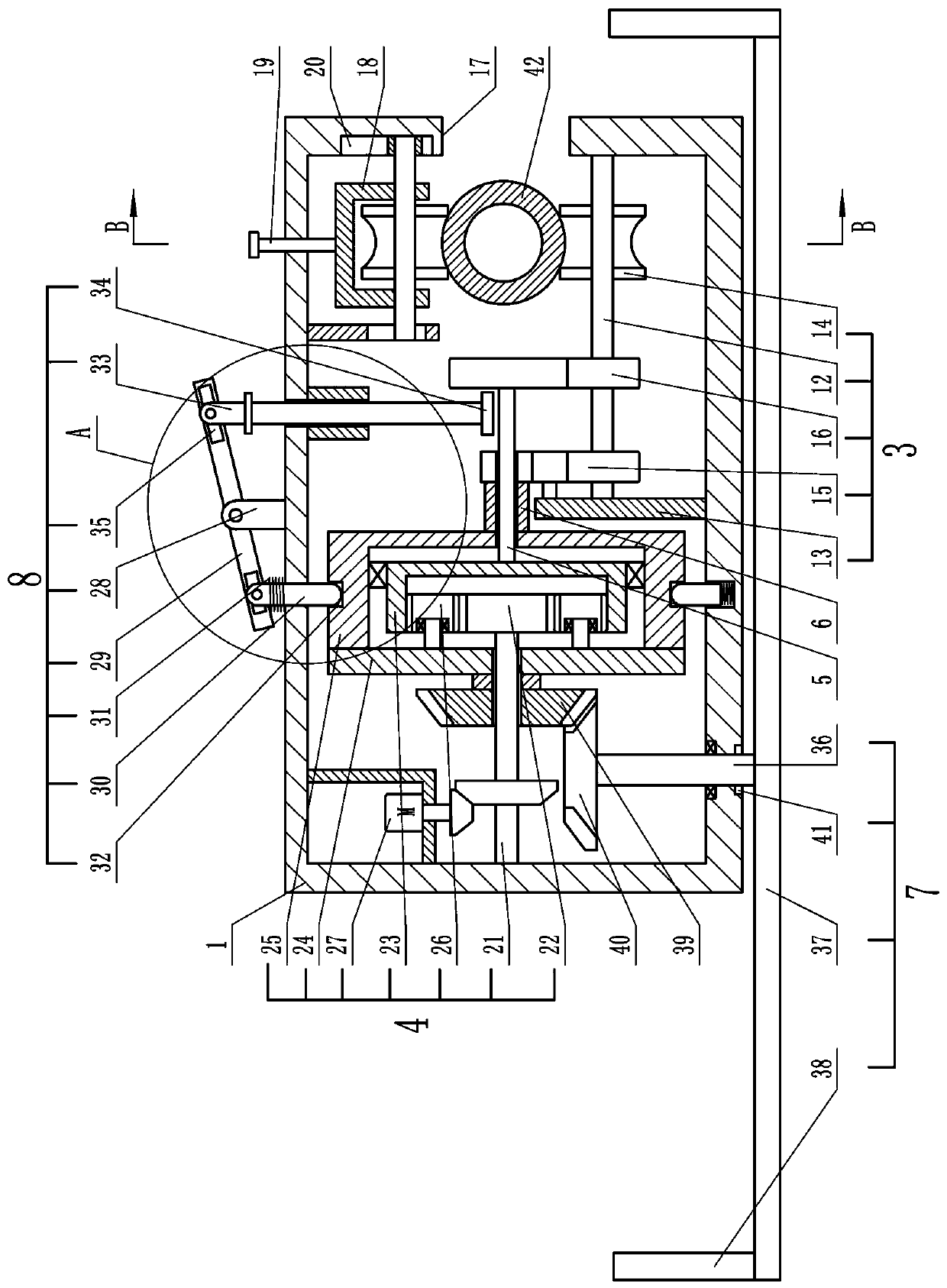
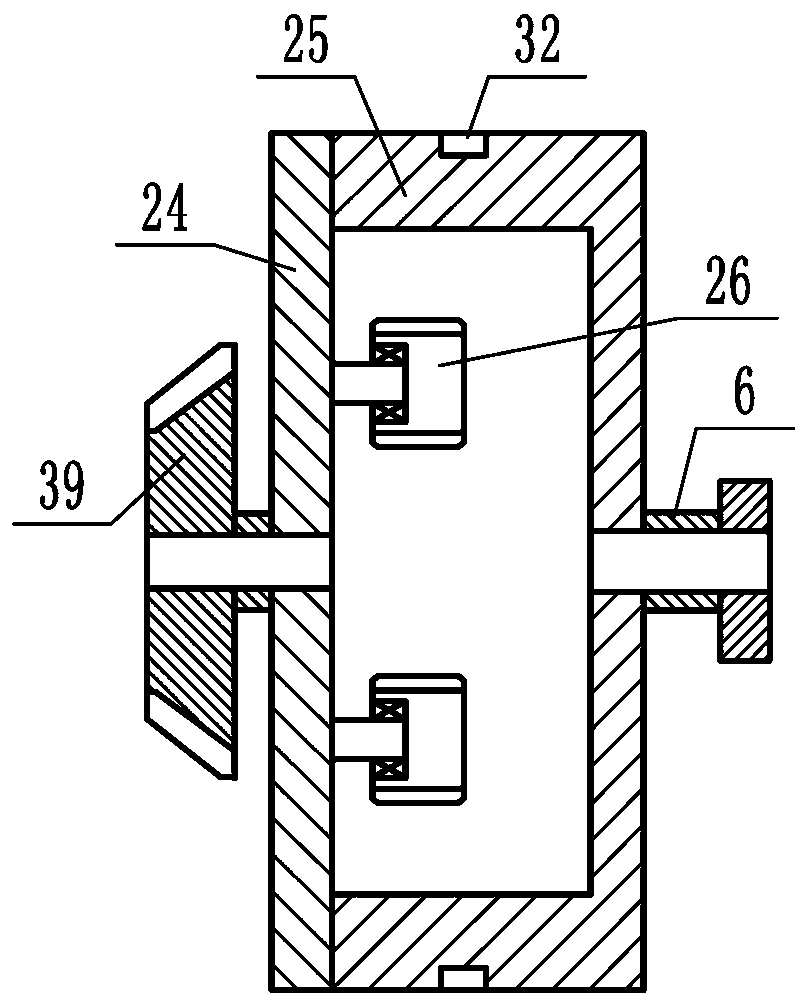
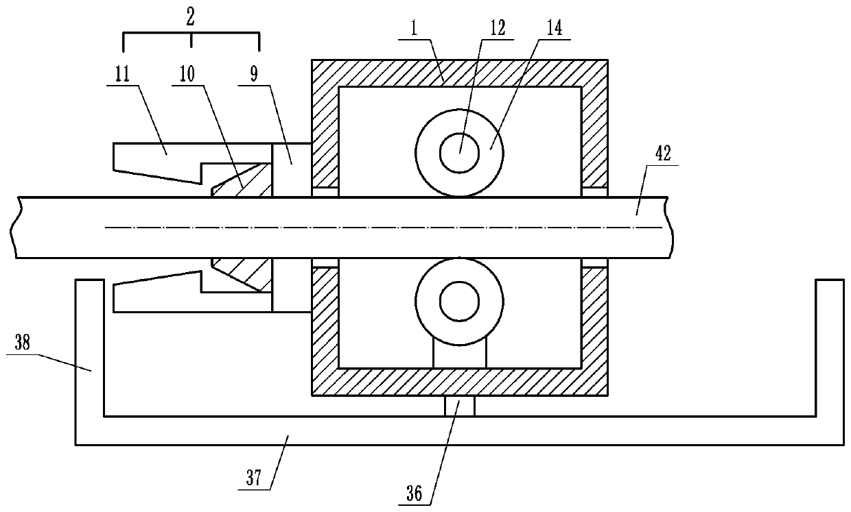
[0016] Depend on Figure 1 to Figure 8 Given, the present invention includes a box body 1, an ice clearing device 2 is installed on the front end of the box body 1, and a walking device that can drive the box body to move forward is installed in the box body 1 on the rear side of the ice cleaning device 2. 3. A driving device 4 is installed in the box body 1. The driving device 4 includes a coaxial first output shaft 5 and a second output shaft 6. The first output shaft 5 and the second output shaft 6 of the driving device 4 are both Connected with the traveling device 3, the end of the second output shaft 6 of the driving device 4 is connected with an ice-beating device 7 capable of knocking out icicles;

[0017] A clutch device 8 is installed between the drive device 4 and the box body 1; when the ice removal device 2...


PUM


Abstract

The invention relates to a power grid deicing device which solves the problems that in the prior art, when ice pillar obstacles exist and smooth walking forwards cannot be conducted, a motor emits heat, and danger is likely to be caused. According to the technical scheme for solving the problems, the device comprises a box body; an ice removing device is arranged on the box body, a walking deviceis arranged in the box body, and a driving device is arranged in the box body; the driving device comprises a first output shaft and a second output shaft; an ice breaking device is arranged at the tail end of the second output shaft; a clutch device is arranged between the driving device and the box body; when the ice removing device normally removes ice, the ice breaking device is in a non-working state, the first output shaft drives the walking device to work, and the ice removing device removes ice wrapping electric wires; when the ice removing device encounters an ice pillar, the clutch device loosens the second output shaft, the second output shaft drives the ice removing device to continuously remove ice, and the ice breaking device breaks the ice pillar; and after the ice pillar iscleaned, the clutch device loosens the first output shaft and fixes the second output shaft again. The device is novel in concept, ingenious in structure and high in practicability.

Description

technical field [0001] The invention relates to the field of grid deicing machinery, in particular to a grid deicing device. Background technique [0002] In winter, the ice on the wire needs to be removed. The existing ice removal device is driven by a motor to walk on the wire. The ice blade of the ice removal device removes the ice on the wire. Obstacles, the ice clearing device cannot move forward smoothly, resulting in the failure of the entire ice clearing work, and at the same time, the motor makes the entire device heat, causing danger. Contents of the invention [0003] In view of the above situation, in order to solve the problems existing in the prior art, the purpose of the present invention is to provide a power grid deicing device, which solves the problem of icicle obstacles encountered in the prior art, and when the motor cannot move forward smoothly, the motor will generate heat, which will easily cause dangerous question. [0004] The technical solution...

Claims


Application Information

Patent Timeline
Patent Type & Authority Applications(China)
IPC IPC(8): H02G7/16H02G1/02
CPCH02G1/02H02G7/16
Inventor 许海涛许春香陈良孙建延王继东
Owner 株洲锐利切削工具股份有限公司
Why Eureka
Eureka Blog
Learn More