
Pressure relief device

A technology of pressure relief device and pressure relief plate, which is applied to valve devices, safety valves, engine components, etc., can solve problems such as potential safety hazards, and achieve high accuracy and large exhaust volume

Active Publication Date: 2015-09-30
BROADWELL SHENZHEN TECH
View PDF6 Cites 7 Cited by
  • Summary
  • Abstract
  • Description
  • Claims
  • Application Information

AI Technical Summary

Problems solved by technology

However, there is a certain error rate in electronic control equipment. Once the control system fails, it may bring great safety hazards.

Method used


Image

  • Pressure relief device
  • Pressure relief device

Examples


Embodiment Construction

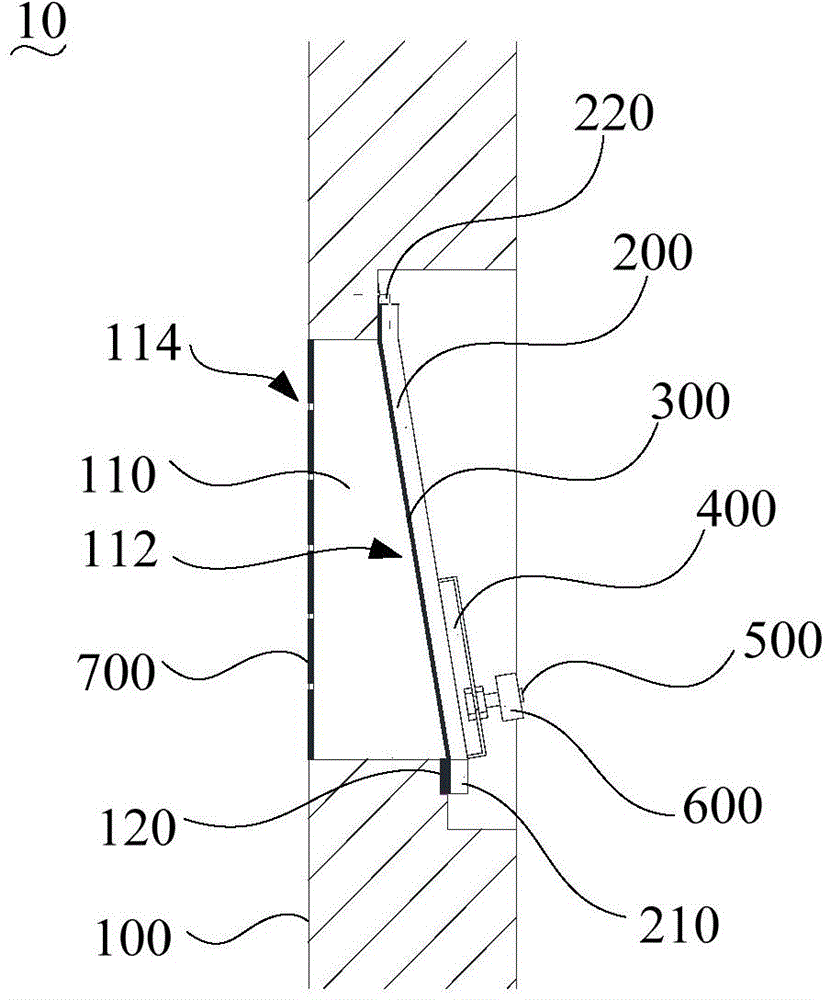
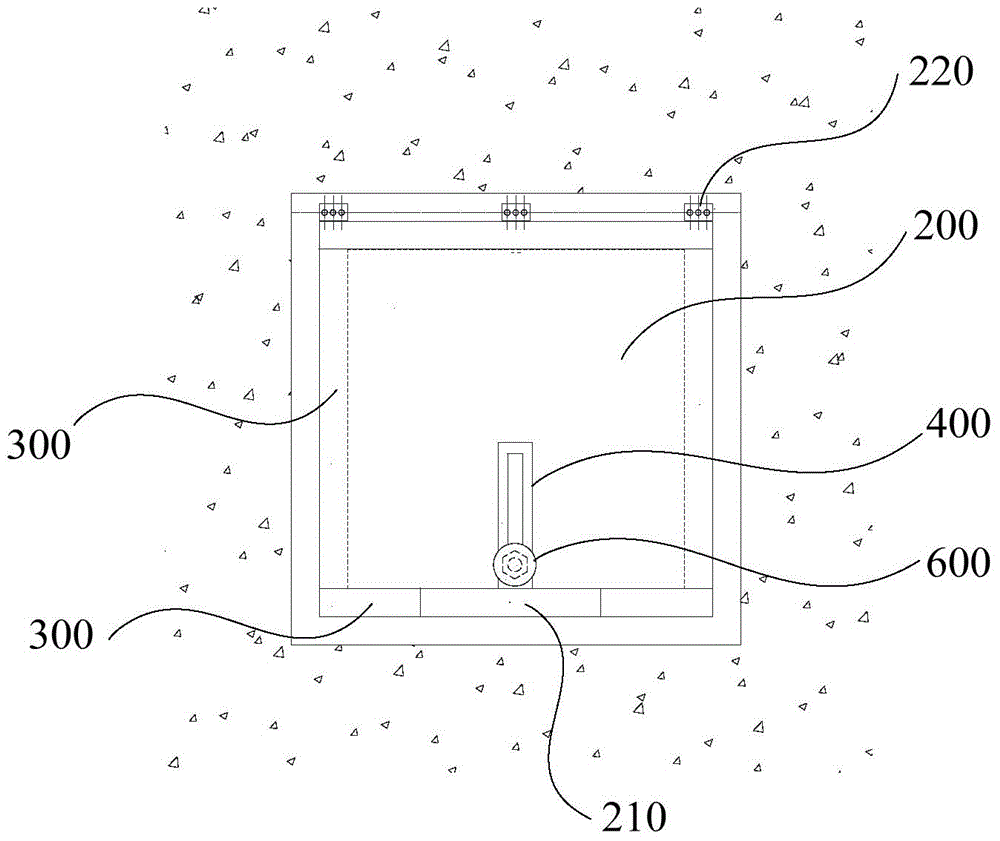
[0021] In order to facilitate the understanding of the present invention, the pressure relief device of the present invention will be more fully described below with reference to the relevant drawings. Preferred embodiments of the invention are shown in the accompanying drawings. However, the present invention can be implemented in many different forms and is not limited to the embodiments described herein. On the contrary, these embodiments are provided to make the understanding of the disclosure of the present invention more thorough and comprehensive.

[0022] It should be noted that when an element is referred to as being “fixed” to another element, it can be directly on the other element or there can also be an intervening element. When an element is referred to as being "connected to" another element, it can be directly connected to the other element or intervening elements may also be present.

[0023] Unless otherwise defined, all technical and scientific terms used ...


PUM


Abstract

A pressure relief device comprises a main inflation part and a pressure relief plate. The main inflation part is provided with a pressure relief port communicated with the outside. The end, used for making contact with the outside, of the pressure relief port is a communicating end, and the other end of the pressure relief port is a free end. The side, used for making contact with the outside, of the main inflation part is provided with a first magnetic strip which is located below the pressure relief port. The pressure relief plate seals the communicating end. The upper end of the pressure relief plate is rotatably connected with the part, located above the pressure relief port, of the main inflation part. The part, overlapped with the first magnetic strip, of the pressure relief plate is provided with a second magnetic strip. The second magnetic strip and the first magnetic strip attract each other. The pressure relief device has the high accuracy rate and can achieve large air flow pressure relief.

Description

technical field [0001] The invention relates to the technical field of pressure relief, in particular to a pressure relief device. Background technique [0002] When there is a pressure difference between the inside and outside of a large-volume sealed space or channel (such as an air film building), in order to ensure safety, the pressure difference needs to be limited within a certain range. Conventional pressure relief devices have too little displacement to be suitable for this type of situation. Existing large-volume sealed spaces or passages use electronic control equipment to limit the air pressure difference between their interior and exterior. However, there is a certain error rate in electronic control equipment, and once the control system fails, it may bring great potential safety hazards. Contents of the invention [0003] Based on this, it is necessary to provide a pressure relief device with high accuracy and capable of realizing pressure relief with a lar...

Claims


Application Information

Patent Timeline
Patent Type & Authority Applications(China)
IPC IPC(8): F16K17/02F16K17/164
Inventor 肖龙王秦杨锋
Owner BROADWELL SHENZHEN TECH
Learn More