
A new type of circular steel pipe pier

A technology of round steel pipes and bridge piers, which is applied in the fields of steel bridge piers and civil engineering in bridge engineering. It can solve problems such as insufficient shear strength, insufficient bending resistance design of bridge piers, and difficult repair and use, so as to speed up road repair and shorten traffic control time. , The effect of short construction period

Active Publication Date: 2016-10-05
HUAQIAO UNIVERSITY
View PDF6 Cites 0 Cited by
  • Summary
  • Abstract
  • Description
  • Claims
  • Application Information

AI Technical Summary

Problems solved by technology

Serious damage to bridge piers may cause the collapse of the bridge, and it is difficult to repair and use it in time after the earthquake, which will bring troubles to rescue and disaster relief after the earthquake, and often cause huge losses
[0003] At this stage, bridge piers at home and abroad generally use reinforced concrete structures. This form of bridge piers has good compressive performance, but poor ductility, and has suffered serious damage in previous earthquakes.
The failure of concrete piers is mainly due to two defects in design and construction: 1) The deficiencies in the bending design of the piers are mainly due to the insufficient configuration of transverse restraint stirrups; 2) The design shear strength of the piers is insufficient, resulting in shear failure prior to ductility bending damage
However, in actual earthquakes, the shell plate at the root of the circular steel pipe pier is prone to local buckling deformation, resulting in a sharp deterioration in the ductility and energy dissipation capacity of the circular steel pipe pier

Method used


Image

  • A new type of circular steel pipe pier
  • A new type of circular steel pipe pier
  • A new type of circular steel pipe pier

Examples


Embodiment Construction

[0024] The present invention will be further described below in conjunction with accompanying drawing:

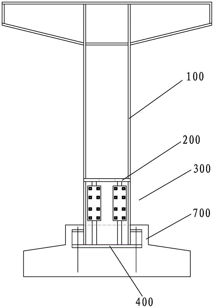
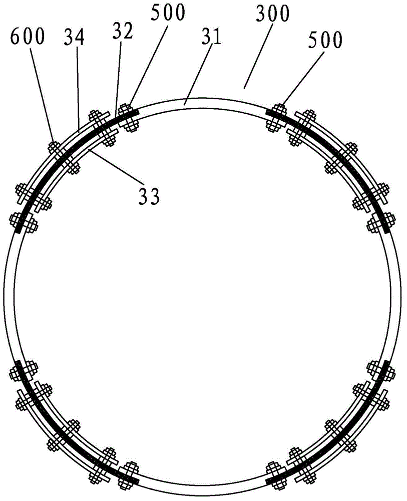
[0025] The invention provides a novel circular steel pipe pier, such as figure 1 As shown, it includes a circular steel pipe pier body 100 , a diaphragm 200 , a buckling-resistant energy-dissipating shell 300 and a bottom plate 400 welded together sequentially from top to bottom.

[0026] The buckling-resistant energy-dissipating shell 300 has a hollow cylindrical shape matching the shape of the round steel pipe pier body 100, the diaphragm 200 is a circular plate matching the shape of the round steel pipe pier body 100, and the round steel pipe pier body 100 and The anti-buckling energy-dissipating shell 300 is welded together through the transverse diaphragm 200, which can ensure the smooth force transmission between the circular steel pipe pier body 100 and the anti-buckling energy-dissipating shell 300, forming a whole to jointly resist external loads; Self-weight and ...


PUM

PropertyMeasurementUnit
yield strengthaaaaaaaaaa

Abstract

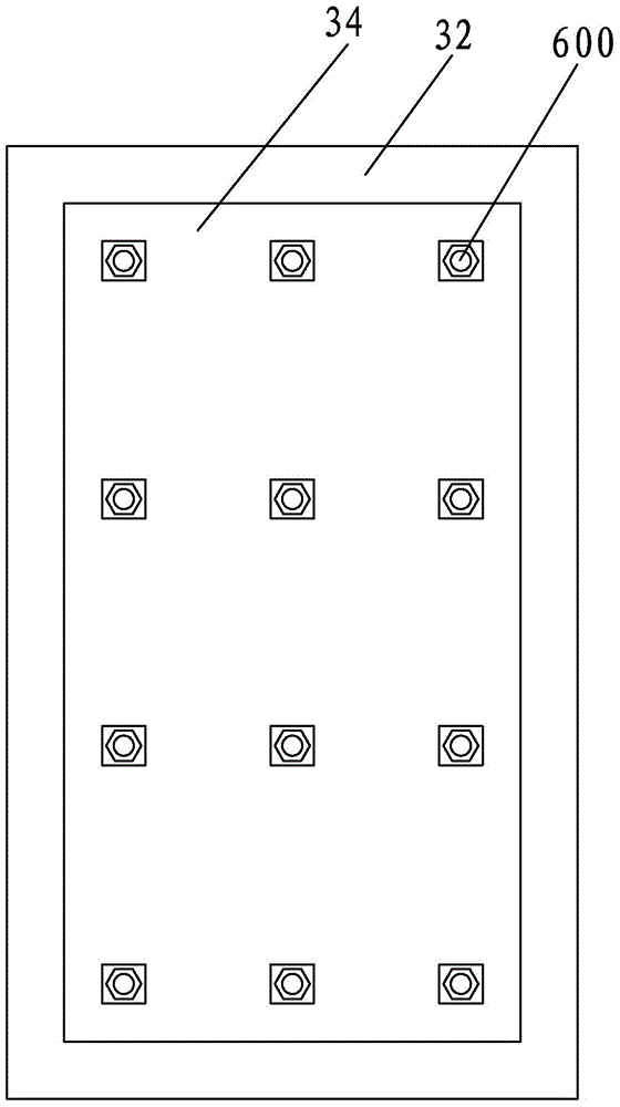
The invention discloses a novel circular steel tube bridge pier, comprising a circular steel tube bridge pier body, a transverse partition, a buckling-restrained energy dissipation shell and a baseplate which are sequentially welded and fixed together from top to bottom. The buckling-restrained energy dissipation shell comprises a plurality of high-strength steel curved plates and a plurality of low-yield-point steel curved plates; the high-strength steel curved plates and the low-yield-point steel curved plates are alternatively distributed to define the buckling-restrained energy dissipation shell, and the outer surfaces of the low-yield-point steel curved plates are tangent to the outer surfaces of the high-strength steel curved plates; an inner restraining curved steel plate and an outer restraining curved steel plate are fixedly locked to the inner and outer sides of each low-yield-point steel curved plate; the radii of the inner and outer restraining curved steel plates are identical with those of the low-yield-point steel curved plates. The circular steel tube bridge pier has good earthquake resistant performances, can be detected and repaired rapidly after earthquakes, and can be conveniently popularized and applied in the practical engineering.

Description

technical field [0001] The invention relates to the energy-dissipating structural form of a steel pier in the field of civil engineering, in particular to a circular steel pipe pier with an anti-buckling energy-dissipating shell at the root, and belongs to the technical field of steel pier in bridge engineering. Background technique [0002] The previous experience of earthquake damage at home and abroad shows that bridges are vulnerable to earthquakes. The bridge pier is the main load-bearing structure of the bridge structure, and its damage plays a decisive role in the damage or even destruction of the bridge structure as a whole. Serious damage to bridge piers may cause bridge collapse, and it is difficult to repair and use in time after the earthquake, which will bring troubles to rescue and disaster relief after the earthquake, and the resulting losses are often very huge. [0003] At present, bridge piers at home and abroad generally adopt the form of reinforced concr...

Claims


Application Information

Patent Timeline
Patent Type & Authority Patents(China)
IPC IPC(8): E01D19/02
Inventor 李海锋韩枫董毓利
Owner HUAQIAO UNIVERSITY
Learn More