Bi-directional flow-limiting valve

A technology of restricting valve and valve core, which is applied in the field of restricting valve, can solve the problems of slow backflow of fluid, large limitation, increase control cost, etc., and achieve the effect of good resistance to reverse flow.

Inactive Publication Date: 2015-10-07
TIANJIN SWICK VALVE IND CO LTD
View PDF6 Cites 9 Cited by
  • Summary
  • Abstract
  • Description
  • Claims
  • Application Information

AI Technical Summary

Problems solved by technology

[0002] Most of the restrictor valves are one-way restrictor valves, which only allow fluid to pass in one direction, and play the role of one-way conduction and reverse flow resistance, but in some fields, after using one-way restrictor valves to restrict flow , requires the fluid to return slowly. For example, in the field of hydraulic machinery, one-way flow limiting valves are commonly used to realize the one-way passage of hydraulic oil and reverse flow resistance, while the return flow of hydraulic oil needs to be controlled separately through other oil passages, so as to realize hydraulic pressure. Reciprocating motion in the form of mechanical rapid ejection and gentle retraction, but this will inevitably increase the control cost, and the pipeline laying is complicated and has great limitations

Method used


Image

  • Bi-directional flow-limiting valve
  • Bi-directional flow-limiting valve
  • Bi-directional flow-limiting valve

Examples


Embodiment Construction

[0019] Specific embodiments of the present invention will be described in detail below in conjunction with the accompanying drawings.

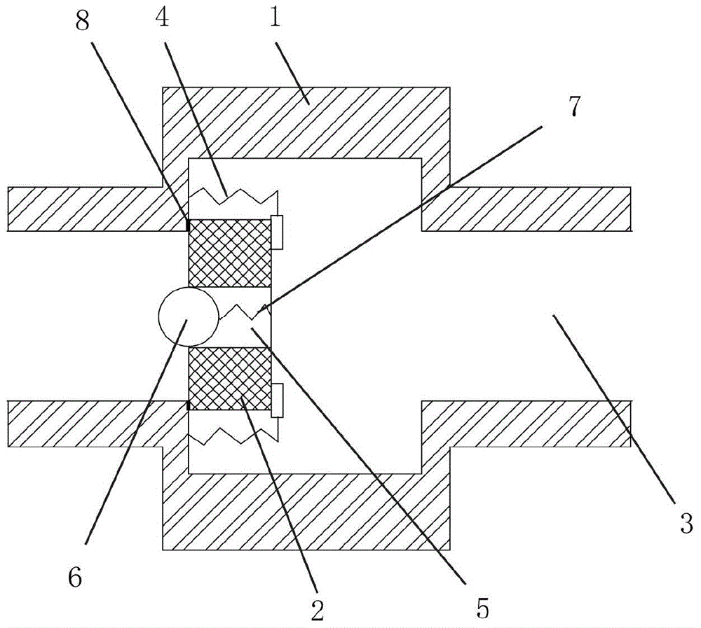
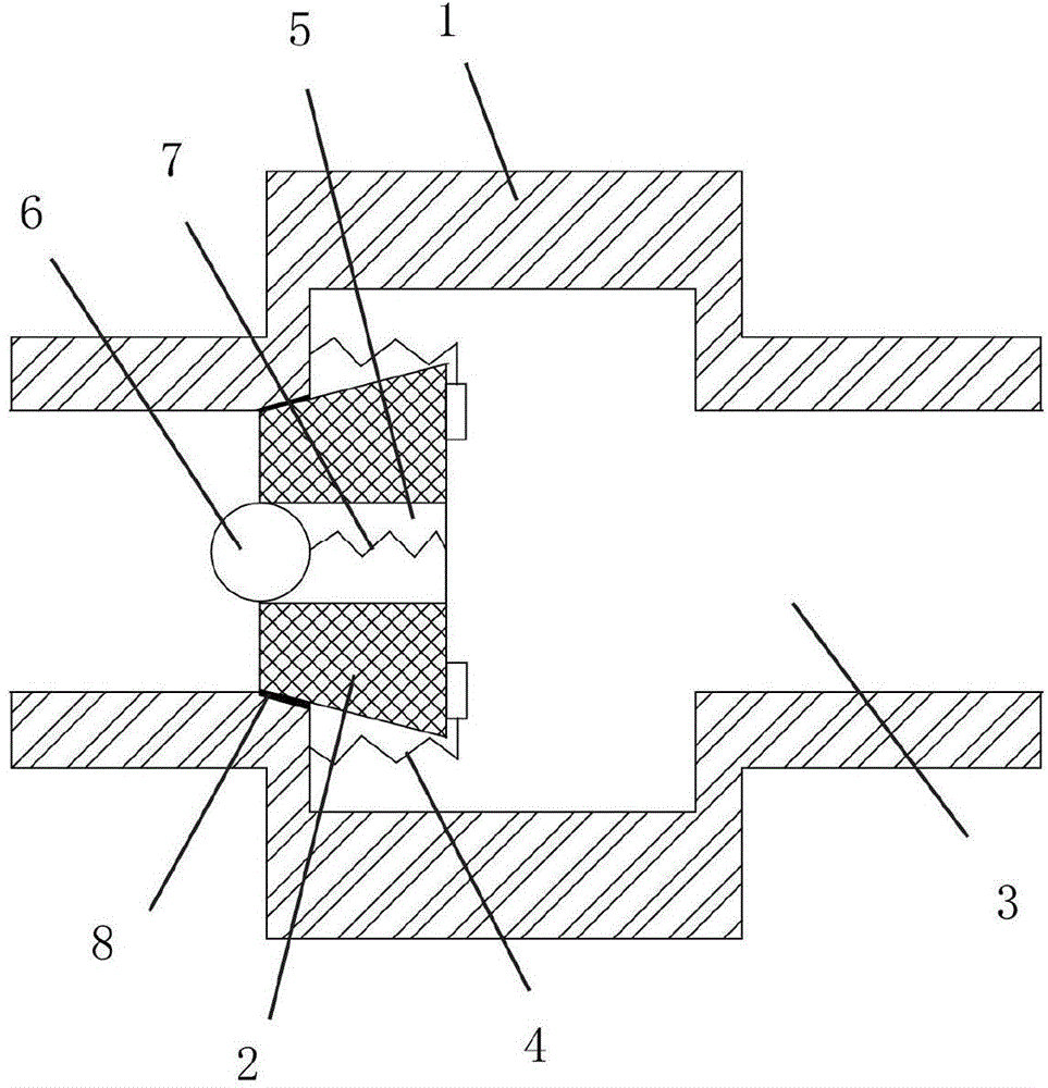
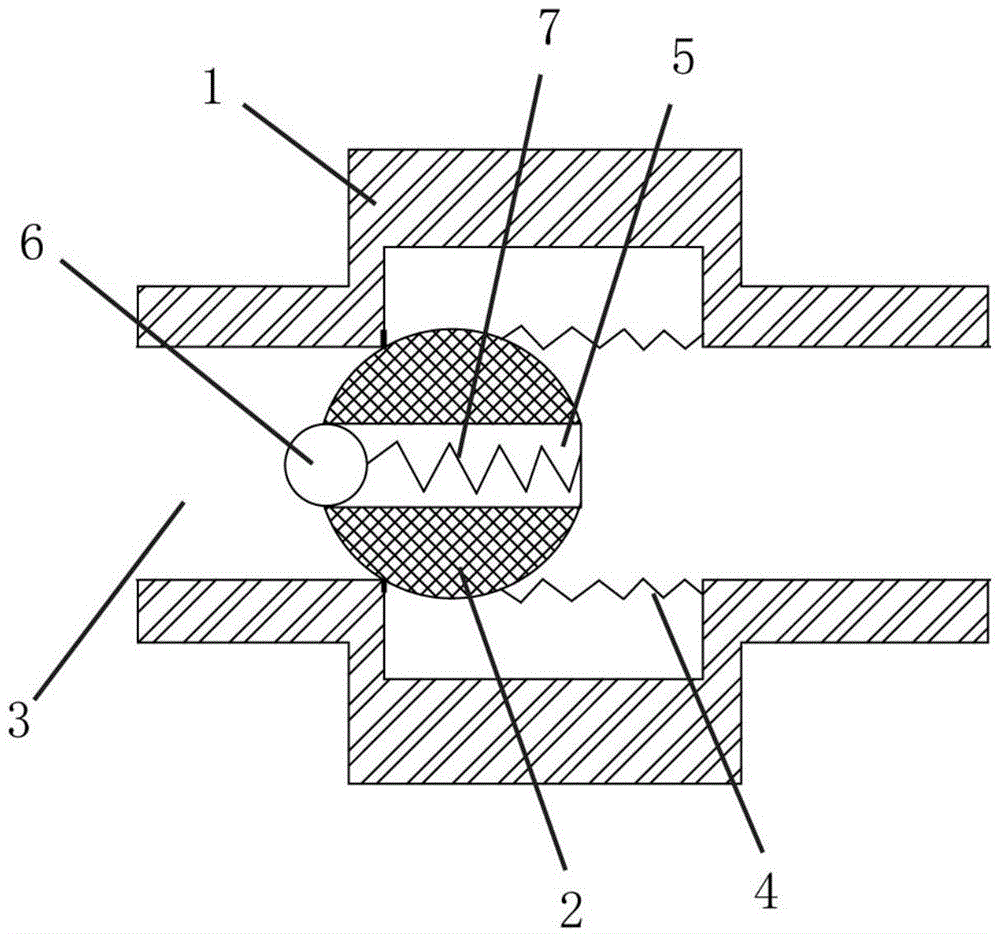
[0020] Such as figure 1 As shown, a two-way flow limiting valve includes a valve body 1 and a valve core 2, the body cavity of the valve body 1 is set as two fluid chambers 3 connected, and one end of the valve core 2 is blocked in one of the fluid chambers 3 There is a first spring 4 connected between the other end of the valve core 2 and the inner wall of the valve body 1. The first spring 4 is used to provide the force for the valve core 2 to block the fluid chamber 3. The through hole 5 in the direction, the through hole 5 on the end wall of the fluid chamber 3 blocked by the spool 2 is blocked with a plug 6, and a second spring 7 is connected between the plug 6 and the spool 2, and the second The spring 7 is used to provide the force of the plug 6 to block the opening of the through hole 5 .

[0021] The two fluid chambers 3 are respect...


PUM


Abstract

The invention provides a bi-directional flow-limiting valve. The bi-directional flow-limiting valve comprises a valve body and a valve core. A body cavity of the valve body is arranged to be two fluid cavities communicated with each other. An inner end opening of one of fluid cavities is plugged by one end of the valve core. First springs are connected between the other end of the valve core and the inner wall of the valve body and used for providing the valve core with force for plugging the fluid cavities. A through hole is formed in the valve core along a radial direction of the valve core. A drain plug is plugged in a hole opening of the through hole, which is plugged by the valve core, of the end wall of one fluid cavity. A second spring is connected between the drain plug and the valve core and used for providing the drain plug with force for plugging the hole opening of the through hole. By cooperation between the valve body and the valve core and cooperation between the through hole and the drain plug, unidirectional circulation of fluids is achieved without backflow. Due to the fact that the cavity diameter of each fluid cavity is larger than hole diameter of the through hole, different fluid cavities are selected as fluid inlets such that different flow rate and flow quantity of fluids can be realized. Sealing rings help to ensure sealing performance of the bi-directional flow-limiting valve such that the back flow-resistant effect is better achieved.

Description

technical field [0001] The invention belongs to the field of valves, in particular to a flow limiting valve. Background technique [0002] Most of the restrictor valves are one-way restrictor valves, which only allow fluid to pass in one direction, and play the role of one-way conduction and reverse flow resistance, but in some fields, after using one-way restrictor valves to restrict flow , requires the fluid to return slowly. For example, in the field of hydraulic machinery, one-way flow limiting valves are often used to realize the one-way passage of hydraulic oil and reverse flow resistance, while the return flow of hydraulic oil needs to be additionally controlled through other oil passages to achieve hydraulic pressure. Reciprocating motion in the form of mechanical rapid ejection and gentle retraction, but this will inevitably increase the control cost, and the pipeline laying is complicated and has great limitations. Contents of the invention [0003] The problem ...

Claims


Application Information

Patent Timeline
Patent Type & Authority Applications(China)
IPC IPC(8): F16K17/20
CPCF16K17/20
Inventor 冯光
Owner TIANJIN SWICK VALVE IND CO LTD
Why Eureka
Try Eureka