
Rotary fixed lamp and mounting method thereof

An installation method and a technology for fixing a plate, which are applied in the directions of fixing lighting devices, light source fixing, lighting devices, etc., can solve the problems of high labor cost, many steps, inability to effectively prevent water leakage, etc., and achieve a simple fixing method and prevent reversal. , the effect of reducing labor costs

Inactive Publication Date: 2015-10-07
SICHUAN SUNRAIN SIGN & DISPLAY SYST
View PDF8 Cites 12 Cited by
  • Summary
  • Abstract
  • Description
  • Claims
  • Application Information

AI Technical Summary

Problems solved by technology

[0004] To sum up, the existing way of installing and fixing the lamp body has many steps and cannot be installed in one step, and the labor cost is high. In addition, it cannot effectively prevent water from leaking from the roof to the bottom of the color steel plate (roof)

Method used


Image

  • Rotary fixed lamp and mounting method thereof
  • Rotary fixed lamp and mounting method thereof
  • Rotary fixed lamp and mounting method thereof

Examples


Embodiment 1

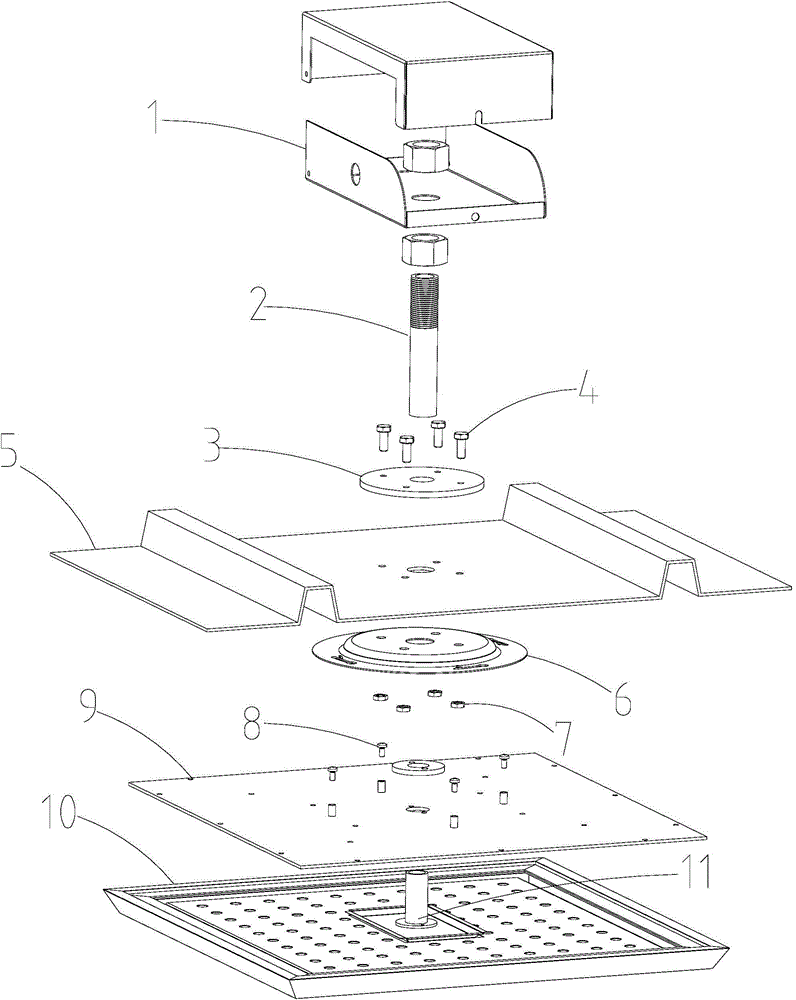
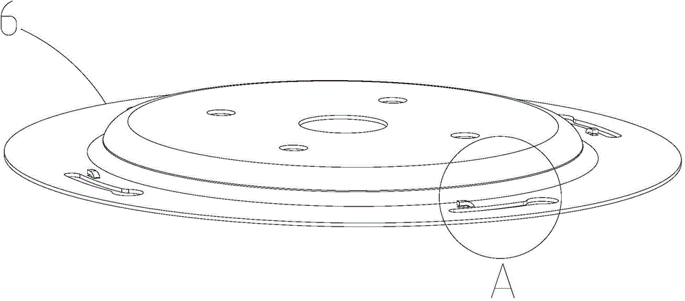
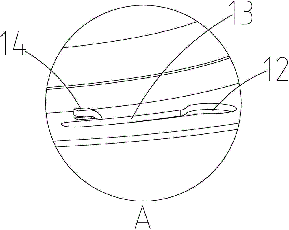
[0043] like figure 1 As shown, a rotating and fixed lamp includes a lamp body 10 and a top plate 5, and a fixing plate 6 is connected to the bottom of the top plate, such as figure 2 shown and combined with image 3 , the fixed plate is provided with an insertion hole 12 and a chute hole 13, the insertion hole communicates with the chute hole, the lamp body is provided with a pan head screw 8, and the aperture of the insertion hole is larger than or It is equal to the diameter of the head of the pan head screw, and the hole diameter of the chute hole is smaller than the head diameter of the pan head screw. After the pan head screw passes through the insertion hole and moves into the chute hole, the lamp body connected to the bottom of the top plate.

[0044] It includes at least two chute holes, the number of pan head screws corresponds to the number of chute holes, and all chute holes are symmetrically distributed around any point on the fixing plate, preferably centered s...

Embodiment 2

[0055] combine Figure 13 Shown, there are following advantages and disadvantages in embodiment 1:

[0056] advantage:

[0057] 1. Only one worker is needed to complete the work during the whole installation process. It greatly saves the cost of workers, especially in the United States, workers start charging when they leave home, until they arrive home after the installation is completed. This saves at least one worker the cost of going back and forth to the installation site and from the installation site to home.

[0058] 2. The installation process of the lamp body is convenient, quick and simple. Insert the lamp body into the corresponding hole and rotate to complete the installation of the lamp body.

[0059] shortcoming

[0060] 1. In the installation step, use nuts to fix and tighten the screws on the top of the color steel plate (top plate). Untightening occurs. The phenomenon of preventing the screw from rotating needs to be solved to ensure that the screw can ...


PUM


Abstract

The invention relates to the field of lamps, in particular to a rotary fixed lamp. The rotary fixed lamp comprises a lamp body and further comprises a top plate. The lower portion of the top plate is connected with a fixed plate, inserting holes and sliding groove holes are formed in the fixed plate, the inserting holes are communicated with the sliding groove holes, pan head screws are arranged on the lamp body, the aperture of the inserting holes is larger than the diameter of the heads of the pan head screws, and the aperture of the sliding groove holes is smaller than the diameter of the heads of the pan head screws. The rotary fixed lamp is simple in fixing mode, a rotary fixing mode is adopted, the fixed plate is added and mounted, the fixed plate is fixedly arranged firstly in the mounting process, then the lamp body is inserted into a mounting hole of the fixed plate from bottom to top, and then the lamp body can be mounted in place by being rotated by a certain angle.

Description

technical field [0001] The invention relates to the field of lamps, in particular to a rotating and fixed lamp and an installation method thereof. Background technique [0002] In the United States, the top of many houses is different from that in China. The installation of lights is based on a single-layer roof through-type, that is, the roof has only one layer of relatively thick color steel plate (unlike domestic roofs that have an outer layer, and the top of the house has a suspended ceiling) type), and foreign power lines are all installed above the roof, therefore, in order to facilitate maintenance and repair, the power box must be installed outside the roof (if it is in China, all power lines are inside the house, it is not necessary place the power box on the outside of the roof). The different housing structures in foreign countries lead to the need for a new installation method of lamps and lanterns that is different from domestic ones. [0003] In addition, the...

Claims


Application Information

Patent Timeline
IPC IPC(8): F21S8/04F21V21/02F21V17/12F21V31/00
CPCF21S8/043F21V17/12F21V21/02F21V31/005
Inventor 李迅刘刚
Owner SICHUAN SUNRAIN SIGN & DISPLAY SYST
Features
  • Generate Ideas
  • Intellectual Property
  • Life Sciences
  • Materials
  • Tech Scout
  • Unparalleled Data Quality
  • Higher Quality Content
  • 60% Fewer Hallucinations
Learn More