Lamp hinge device

A technology of hinge devices and lamps, applied in lighting devices, lighting auxiliary devices, components of lighting devices, etc., can solve the problems of rough and simple, complex production costs, loosening or slipping, etc., and achieve high safety performance and strong stability. , The connection is firm and stable

Inactive Publication Date: 2015-10-07
金 容范
View PDF8 Cites 5 Cited by
  • Summary
  • Abstract
  • Description
  • Claims
  • Application Information

AI Technical Summary

Problems solved by technology

[0002] Lamps are indispensable electrical appliances in people's daily work and life. With the improvement of living standards, people's requirements for lamps are getting higher and higher, such as table lamps, floor lamps, wall lamps and other lamps. 1. The irradiation angle can be flexible and changeable, and various irradiation angles can be converted according to personal preferences. Some existing lamps can also change the irradiation angle through the joint structure, but the existing joint structure is often too complicated so that the production cost is high, and The operation steps are cumbersome and complicated; some joint structures are too rough and simple, and the angle of the adjustment rod is only adjusted by the tightness of the screw at the joint part. Long-term use is prone to loosening or slipping, making the adjustment rods unable to be firmly positioned and not durable enough. Durable, affecting the service life, and the screw needs to be loosened and tightened before and after turning the adjustment lever, the operation is cumbersome and time-consuming

Method used


Image

  • Lamp hinge device
  • Lamp hinge device

Examples


Embodiment Construction

[0016] It should be understood that the specific embodiments described here are only used to explain the present invention, not to limit the present invention.

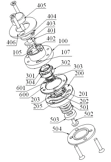
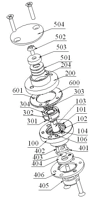
[0017] refer to Figure 1 to Figure 2 , propose an embodiment of the hinge device of the lamp of the present invention, the lamp has a first adjusting rod and a second adjusting rod that can rotate mutually so as to adjust the irradiation angle of the lamp head, and the hinge device is arranged on the first adjusting rod, the second adjusting rod The connection of the adjusting rods enables forward and reverse rotation between the first adjusting rod and the second adjusting rod to adjust the irradiation angle of the lamp head.

[0018] The hinge device includes a first adjusting seat 100 fixedly embedded on the first adjusting rod, a second adjusting seat 200 fixedly embedded on the second adjusting rod, and is arranged between the first adjusting seat 100 and the second adjusting seat 200 and can make the second adj...


PUM


Abstract

The invention discloses a lamp hinge device. According to the lamp hinge device, a lamp is provided with a first adjusting rod and a second adjusting rod which are capable of mutually rotating to adjust the illuminating angles of a lamp holder, the hinge device is arranged on the connection position of the first adjusting rod and the second adjusting rod to enable the happening of front and reverse rotation between the first adjusting rod and the second adjusting rod, and then the illuminating angles of the lamp holder are adjusted; the hinge device comprises a first adjusting base, a second adjusting base, a gear device, a friction plate, a button component and a connection component, wherein the first adjusting base is embedded into the first adjusting rod, the second adjusting base is embedded into the second adjusting rod, the gear device is arranged between the first adjusting base and the second adjusting base and capable of enabling the happening of relative rotation between the first adjusting base and the second adjusting base, the friction plate is made of wear-resistant materials and clamped between the first adjusting base and the second adjusting base, and the functions of preventing abrasion and filling gaps to enable connection to be firm and stable are achieved by the friction plate, the button component is arranged on the outer side of the first adjusting base and capable of pushing the gear device to move, and the connection component is arranged on the outer side of the second adjusting base.

Description

technical field [0001] The invention relates to the technical field of lamps, in particular to a hinge device of a lamp. Background technique [0002] Lamps are indispensable electrical appliances in people's daily work and life. With the improvement of living standards, people's requirements for lamps are getting higher and higher, such as table lamps, floor lamps, wall lamps and other lamps. 1. The irradiation angle can be flexible and changeable, and various irradiation angles can be converted according to personal preferences. Some existing lamps can also change the irradiation angle through the joint structure, but the existing joint structure is often too complicated so that the production cost is high, and The operation steps are cumbersome and complicated; some joint structures are too rough and simple, and the angle of the adjustment rod is only adjusted by the tightness of the screw at the joint part. Long-term use is prone to loosening or slipping, making the adju...

Claims


Application Information

Patent Timeline
Patent Type & Authority Applications(China)
IPC IPC(8): F21V14/02F21V21/14
CPCF21V14/02F21V21/14
Inventor 金容范
Owner 金 容范
Why Eureka
Try Eureka