

A heat recovery type sewage source heat pump system
A sewage source heat pump and heat recovery technology, applied in heat pumps, lighting and heating equipment, mechanical equipment, etc., can solve the problems of low utilization rate of heat energy of discharged sewage, and achieve the effect of high efficiency utilization and high energy efficiency ratio of units
- Summary
- Abstract
- Description
- Claims
- Application Information
AI Technical Summary
Problems solved by technology
Method used
Image

Examples
Embodiment 1
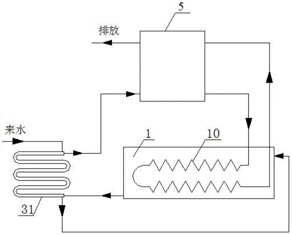
[0048] Such as Figure 4 Shown is a schematic structural diagram of Embodiment 1 of a heat recovery type sewage source heat pump system provided by the present invention, which is composed of Figure 4 It can be seen that, in the embodiment of the heat recovery type sewage source heat pump system provided by the present invention, the first sewage pump 21 is arranged between the water inlet of the inner pipe of the primary casing heat exchanger 31 and the sewage outlet of the biochemical pool 1; A second sewage pump 22 is arranged between the water outlet of the outer casing of the primary casing heat exchanger 31 and the water inlet of the biochemical pool 1 .
[0049] The heating coil 10 is a refrigerant heating coil. The heat pump unit 5 is replaced by an evaporator 6 , a throttle element 7 and a compressor 8 . The water outlet of the inner tube of the primary casing heat exchanger 31 is connected to the water source side water inlet of the evaporator 6, and the water sou...
Embodiment 2
[0052] Such as Figure 5 Shown is a schematic structural diagram of Embodiment 2 of a heat recovery type sewage source heat pump system provided by the present invention. Figure 5 It can be seen that, in the embodiment of the heat recovery type sewage source heat pump system provided by the present invention, the first sewage pump 21 is arranged between the water inlet of the inner pipe of the primary casing heat exchanger 31 and the sewage outlet of the biochemical pool 1; A second sewage pump 22 is arranged between the water outlet of the outer casing and the water inlet of the biochemical pool 1 .
[0053] The heating coil 10 is a hot water heating coil. The heat pump unit 5 includes an evaporator 6 , a throttle element 7 , a compressor 8 and a condenser 9 . The water outlet of the inner tube of the primary casing heat exchanger 31 is connected to the water source side water inlet of the evaporator 6, and the water source side water outlet of the evaporator 6 discharges ...
Embodiment 3
[0056] Such as Figure 6 Shown is a schematic structural diagram of Embodiment 3 of a heat recovery type sewage source heat pump system provided by the present invention. Figure 4 It can be seen that, in the embodiment of the heat recovery type sewage source heat pump system provided by the present invention, the first sewage pump 21 is arranged between the water inlet of the inner pipe of the primary casing heat exchanger 31 and the sewage outlet of the biochemical pool 1; A second sewage pump 22 is arranged between the water outlet of the outer casing and the water inlet of the biochemical pool 1 .
[0057] The heating coil 10 is a refrigerant heating coil. The heat pump unit 5 is replaced by an evaporator 6 , a throttle element 7 and a compressor 8 .
[0058] A secondary casing heat exchanger 32 is arranged between the primary casing heat exchanger 31 and the evaporator 6, and the water outlet of the inner tube of the primary casing heat exchanger 31 is connected to the ...
PUM
 Abstract
Description
Claims
Application Information