Metering valve for additives at risk of freezing

A metering valve and valve body technology, applied in the field of metering valves, to achieve the effect of ensuring safe positioning

Active Publication Date: 2015-10-07
CONTINENTAL AUTOMOTIVE GMBH
View PDF4 Cites 0 Cited by
  • Summary
  • Abstract
  • Description
  • Claims
  • Application Information

AI Technical Summary

Problems solved by technology

[0005] The purpose of the present invention is to solve or at least alleviate the technical problems associated with the prior art

Method used


Image

  • Metering valve for additives at risk of freezing
  • Metering valve for additives at risk of freezing
  • Metering valve for additives at risk of freezing

Examples


Embodiment Construction

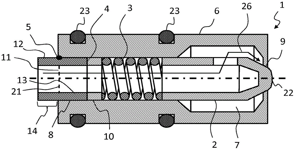
[0027] figure 1A metering valve 1 is shown with a valve housing 6 through which a channel 7 extends. The valve body 2 is arranged in the channel 7 . Valve body 2 is tensioned by spring 3 in metering valve 1 or in valve housing 6 or in channel 7 . To this end, the spring 3 is supported against the calibration body 4 . Calibration body 4 , spring 3 and valve body 2 are inserted into valve housing 6 via opening 11 of channel 7 . The calibrating body 4 is located in the channel section 8 of the channel 7 here. The spring 3 exerts a defined force on the valve body 2 which presses the valve body 2 against the closing seat 9 and thereby closes the metering valve 1 . The valve body 2 can be moved by a drive not shown against the spring force exerted by the spring 3, so that the valve body 2 moves away from the closing seat 9 and thereby opens the flow path 10 through the metering valve 1 from the inlet 21 to the outlet 22 and by This opens metering valve 1. The metering valve 1 ...


PUM


Abstract

The invention relates to a metering valve (1), at least comprising a valve housing (6), a channel (7), a valve body (2), which can be moved in order to open and close the metering valve (1), and a spring (3), which applies a spring force to the valve body (2) and thus keeps the valve body (2) in a rest position, wherein the spring (3) is supported on at least one calibration body (4), the valve body (2), the spring (3), and the at least one calibration body (4) are arranged in the channel (7), and the at least one calibration body (4) is supported by a supporting component (13), which is fastened in the valve housing (6) by means of a material-bonding connection (5), wherein a segment (14) of the supporting component (13) protrudes from the valve housing (6).

Description

technical field [0001] The invention relates to a metering valve. Such a metering valve can be used to meter liquid from a reservoir under pressure. Background technique [0002] Dosing valves are particularly suitable for metering liquid additives that are at risk of freezing. Such liquid additives with a risk of freezing are, for example, aqueous urea solutions. Aqueous urea solutions are commonly used in the motor vehicle sector for exhaust gas purification of exhaust gas treatment systems. In recent years, in motor vehicles, SCR methods (Selective Catalytic Reduction) have been increasingly used in exhaust gas treatment systems for cleaning the exhaust gases of internal combustion engines. In this method, nitrogen oxides in the exhaust are reduced to form harmless substances. For this purpose, an aqueous urea solution as reducing agent precursor or ammonia as reducing agent is supplied to the exhaust gas treatment system. The aqueous urea solution is converted therm...

Claims


Application Information

Patent Timeline
IPC IPC(8): F01N3/20
CPCF01N3/208F01N2610/02F01N2610/1453F02M61/02F02M61/168Y02T10/24Y02T10/12F01N3/20F16K3/00F16K3/20F16K1/32
Inventor G·W·黑泽曼
Owner CONTINENTAL AUTOMOTIVE GMBH
Why Eureka
Try Eureka