Hydraulic machine

a technology of hydraulic machine and pressure plate, which is applied in the direction of rotary or oscillating piston engine, engine lubrication, rotary piston engine, etc., can solve the problems of relatively large space, relatively expensive manufacturing of machine, and relative complicated design of pressure plate, etc., to achieve large force transfer, large surface area, and large deformation of sealing

Active Publication Date: 2013-05-21
DANFOSS PAUER SOLYUSHENS APS
View PDF21 Cites 0 Cited by
  • Summary
  • Abstract
  • Description
  • Claims
  • Application Information

AI Technical Summary

Benefits of technology

[0011]Preferably, the sealing is arranged in an annular groove, the position of the sealing in the radial direction being clearance-subjected. This clearance-subjected position is achieved in that the groove has a large width than the sealing. The groove can be made either in the housing or in the rotary slide valve. In order to ensure an axial prestress of the sealing, the depth of the groove should be smaller than the thickness of the sealing. The groove ensures a safe positioning of the sealing. The clearance-subjected position causes that the sealing can be acted upon by the pressure of the working medium. This pressure causes a radial deformation of the sealing and thus an increased pressure against the rotary slide valve, which is then pressed more firmly against the valve plate. When the working pressure is increasing, the rotary slide valve will be pressed against the valve plate with an increasing force, so that a tight connection between the rotary slide valve and the valve plate remains ensured.
[0012]Advantageously, the sealing has two areas, the housing-side area being made to be elastic and the area facing the valve plate comprising a friction-reducing material. Thus, the areas lie next to one another in the axial direction. The housing-side area can, for example, be made of a rubber material. The other area may, for example, comprise Teflon, PTFE or the like, to keep the wear and the friction between the sealing and the rotary slide valve small. The required tightness is ensured by the housing-side area. Further, this area can be deformed by the pressurised hydraulic fluid and transfer this deformation in the form of an increased pressure force to the rotary slide valve. At the same time, it provides a static prestressing, which is particularly favourable when starting the machine. The sealing can be made in one piece. However, it is also possible to make it of several pieces, for example of two pieces, one part being the first area and one part being the second area.
[0013]Preferably, the sealing is unrotatably held in the housing. Thus, in relation to the housing the sealing performs no relative movement. The sealing can therefore be held relatively firmly in the housing. It is sufficient that only the surface of the sealing, which is in contact with the rotary slide valve, is provided with a low-frictional and wear resistant material. Thus, it is possible to make a relatively large area of the sealing elastic, which is advantageous for the desired function and tightness.
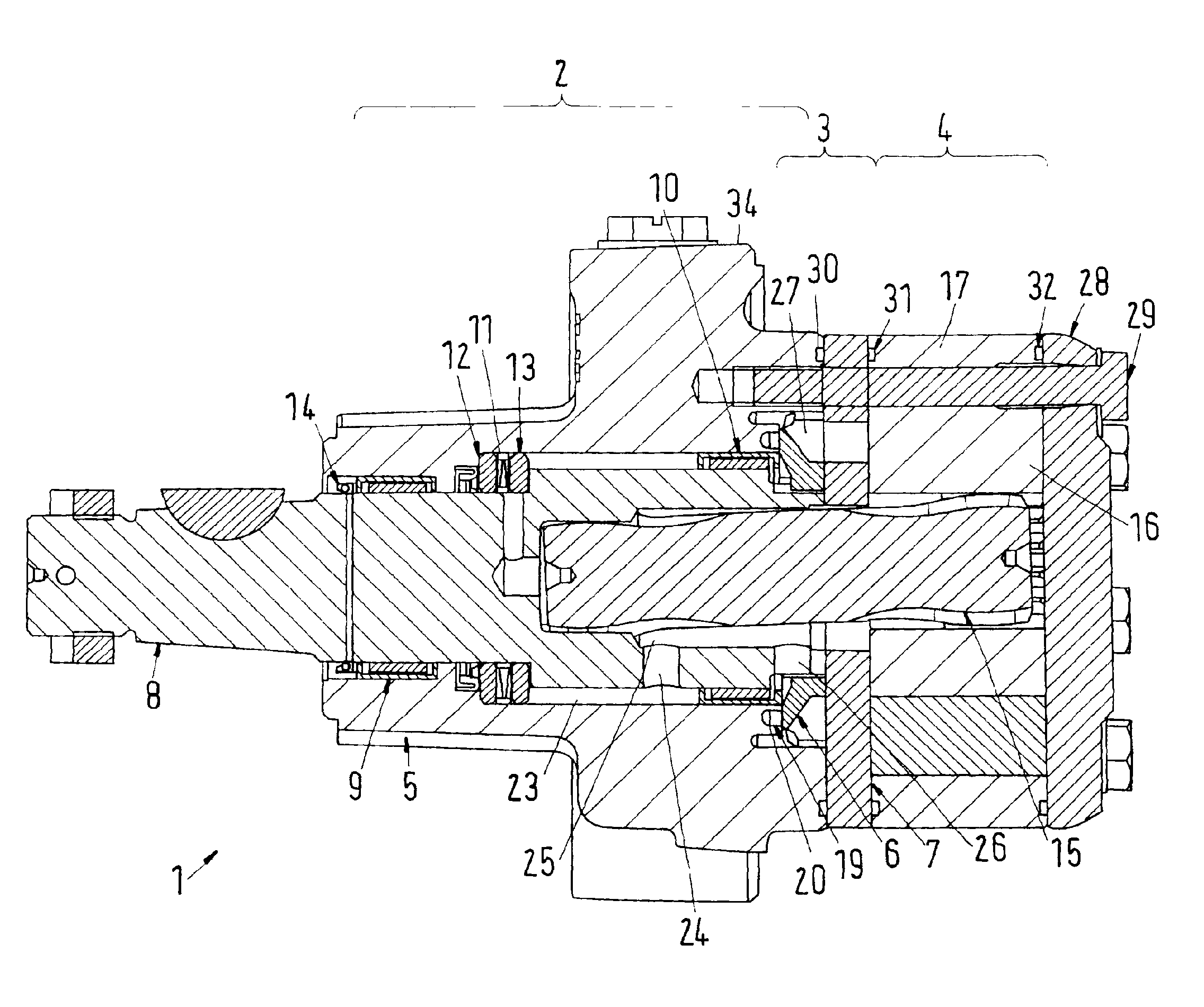
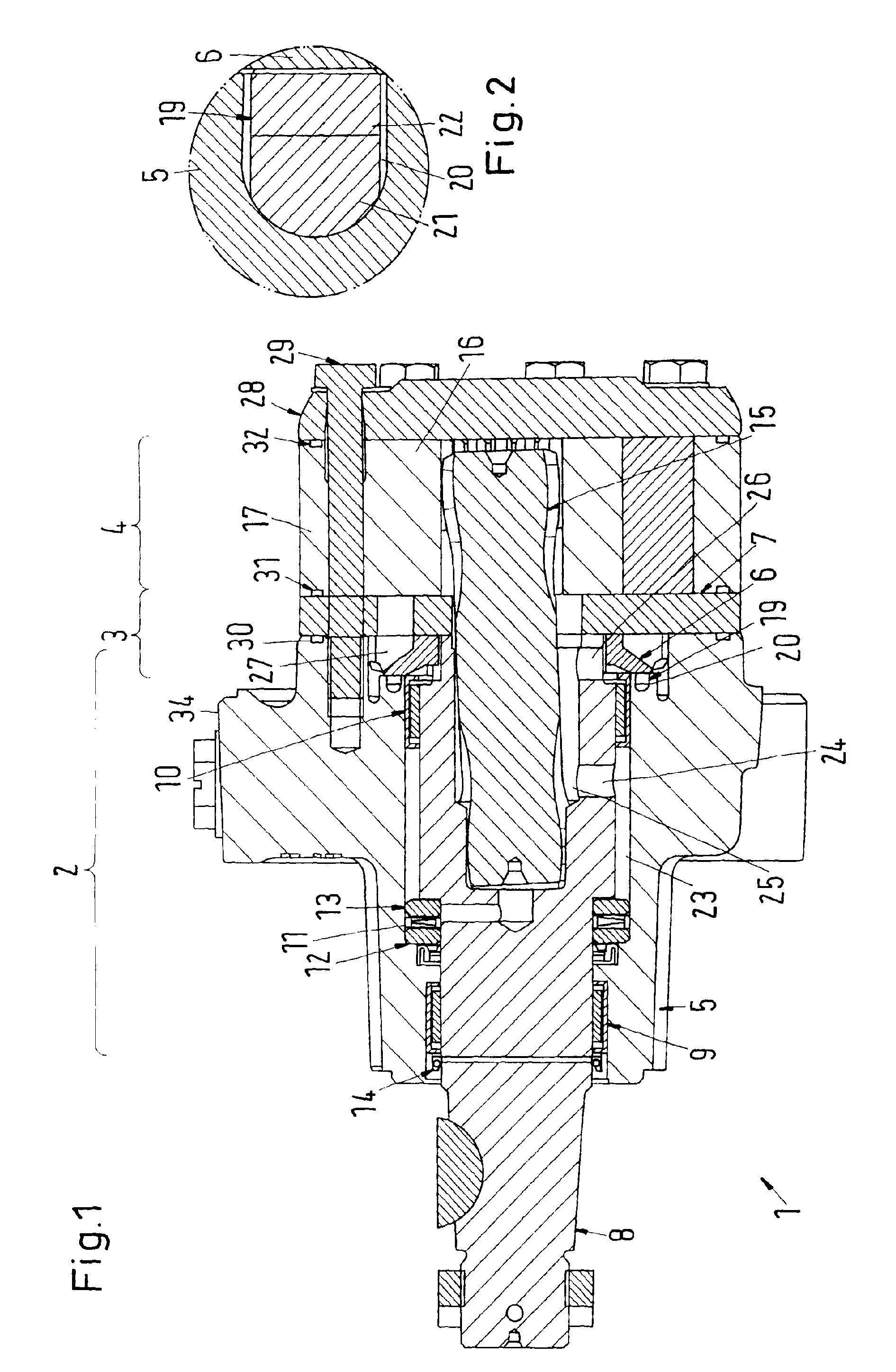
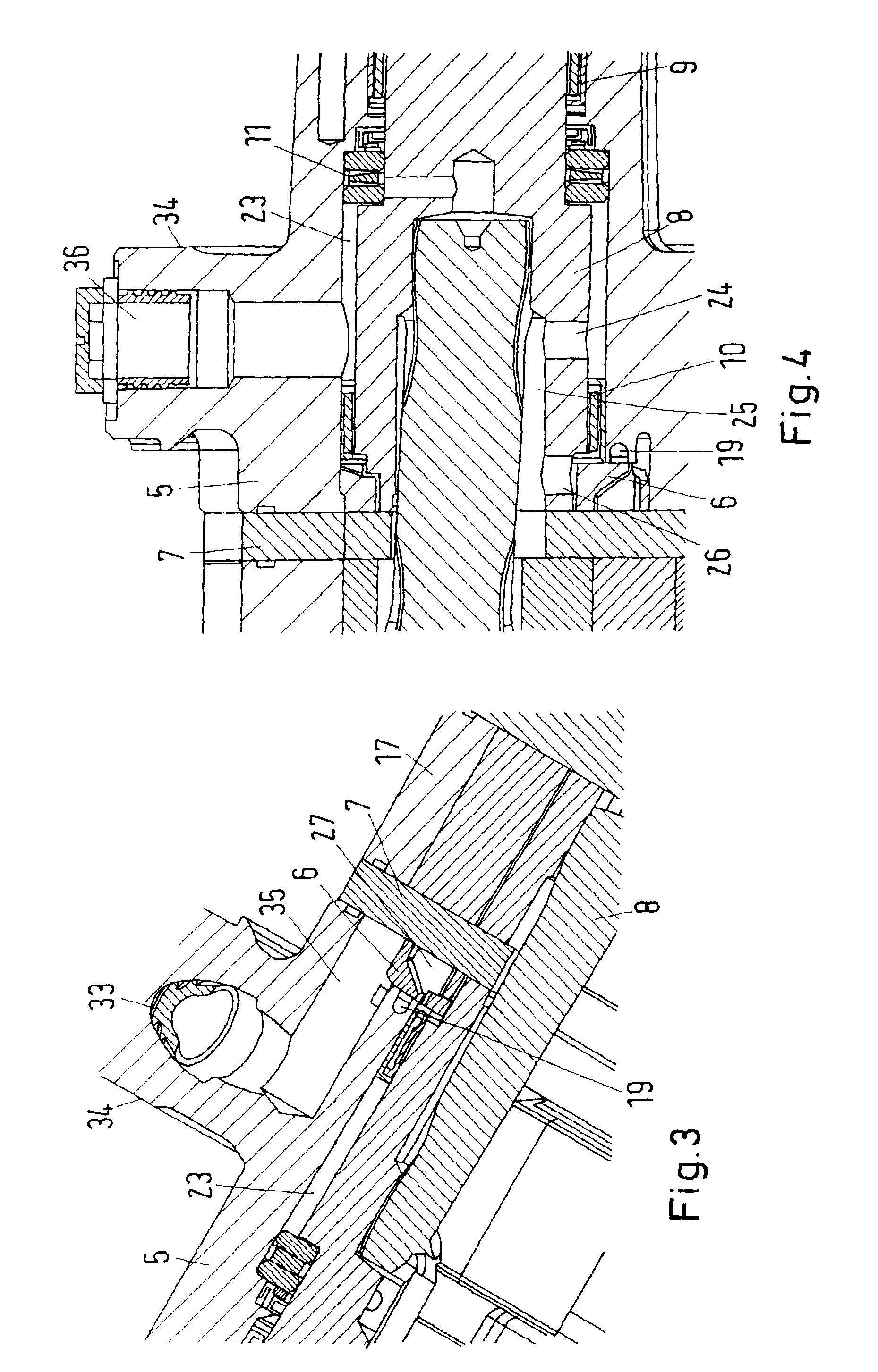
[0015]Preferably, in the groove the sealing separates an area that is connected to the inlet connection from an area that is connected to the outlet connection. Depending on the rotation direction of the machine either one side or the other of the sealing will be acted upon by the increased pressure of the working medium. The working medium with low pressure is on the other side. Thus, depending on the rotation direction, the sealing is acted upon by pressure either radially inwards or radially outwards, the clearance-subjected position of the sealing in the groove ensuring that a relatively large surface of the sealing can be acted upon by pressure. This causes that a relatively large deformation of the sealing or a relatively large force transfer via the sealing to the rotary slide valve is possible, so that the rotary slide valve is reliably pressed against the valve plate. The radial deformation and the displacement of the sealing also increase the surface of the rotary slide valve that can be acted upon by the pressure of the working medium. This presses the rotary slide valve against the valve plate with an increased force.
[0016]Preferably, the drive shaft has a channel, a working medium being transportable to the rotary slide valve through the channel. The space required in the housing for the supply and discharge of the hydraulic fluid is reduced in that this channel is arranged in the drive shaft. The space required for the hydraulic machine can be further reduced.
[0017]It is particularly preferred that the channel connects an outer annular chamber that is formed between the housing and the drive shaft to an inner annular chamber that is formed between the drive shaft and an articulated shaft. As the articulated shaft performs an orbiting movement, an annular chamber is provided between the articulated shaft and the drive shaft. The outer annular chamber between the housing and the drive shaft thus permits a manufacturing with relatively large tolerances, as an outer diameter of the drive shaft does not have to be exactly adapted to an inner diameter of the housing. This makes the design of the hydraulic machine very cost effective.

Problems solved by technology

In order that the pressure plate can also supply a sufficient pressure against the rotary slide valve during a reversal of the rotation direction of the machine, during which also the pressures at the inlet connection and the outlet connection are reversed, a relatively complicated design of the pressure plate is required.
This causes on the one side that a relatively large space is required, and on the other side the manufacturing of the machine is also rather cost intensive.

Method used


Image

  • Hydraulic machine
  • Hydraulic machine
  • Hydraulic machine

Examples


Embodiment Construction

[0024]FIG. 1 shows a schematic view of a hydraulic machine 1 that comprises a housing section 2, a commutation section 3 and a gear wheel section 4. A housing 5 is arranged in the housing section 2. The commutation section 3 comprises a rotary slide valve 6 and a valve plate 7. The rotary slide valve 6 is located inside the housing 5, so that the housing section 2 and the commutation section 3 overlap each other. The rotary slide valve 6 is unrotatably held on a drive shaft 8 that is supported in the housing by means of two axial bearings 9, 10. Via an axial bearing 11 that comprises a first rotating disc 12 and a second rotating disc 13 an axial movement of the drive shaft 8 in relation to the housing 5 is prevented. For the sealing towards the environment, a sealing 14 is arranged between the housing 5 and the drive shaft 8.

[0025]Via an articulated shaft 15, the drive shaft 8 is connected to a gear wheel 16 that is supported to be orbiting in a gear ring 17. For this purpose, the ...


PUM


Abstract

The invention relates to a hydraulic machine comprising a housing section with a housing, a commutation section and a gear wheel section, the gear wheel section comprising a gear wheel set with an internally toothed gear ring and an externally toothed gear wheel, which engage each other and form working chambers that are connected to at least one inlet connection and at least one outlet connection via the commutation section that comprises a rotary slide valve and a valve plate. It is endeavored to provide such a hydraulic machine that requires only little space. For this purpose, a sealing is arranged between the rotary slide valve and the housing.

Description

CROSS REFERENCE TO RELATED APPLICATION[0001]Applicant hereby claims foreign priority benefits under U.S.C. §119 from German Patent Application No. 10 2008 063 500.6 filed on Dec. 17, 2008, the contents of which are incorporated by reference herein.FIELD OF THE INVENTION[0002]The invention relates to a hydraulic machine comprising a housing section with a housing, a commutation section and a gear wheel section, the gear wheel section comprising a gear wheel set with an internally toothed gear ring and an externally toothed gear wheel, which engage each other and form working chambers that are connected to at least one inlet connection and at least one outlet connection via the commutation section that comprises a rotary slide valve and a valve plate.BACKGROUND OF THE INVENTION[0003]Such a hydraulic machine is, for example, known from DE 195 20 405 C2 and DE 195 20 402 C2. In such machines, the gear wheel orbits inside the gear ring. For this purpose, a tooth number difference exists ...

Claims


Application Information

Patent Timeline
Patent Type & Authority Patents(United States)
IPC IPC(8): F01C1/02
CPCF04C14/12F04C15/0019F04C15/0034F04C15/064F04C2/103
Inventor LARSEN, HENNING LUNDLARSEN, PETER RANDLEV
Owner DANFOSS PAUER SOLYUSHENS APS
Why Eureka
Try Eureka