Multifunctional paper shredder

a multi-functional, paper shredder technology, applied in grain treatment, manufacturing tools, applications, etc., can solve the problems of inability to shredded or scrape successfully, roller blades that pulsate severely, and cannot be shredded or scrapped successfully, so as to achieve a smoother angle, reduce the effect of height and width

Inactive Publication Date: 2007-05-08
AURORA GLOBAL INVESTMENT
View PDF5 Cites 54 Cited by
  • Summary
  • Abstract
  • Description
  • Claims
  • Application Information

AI Technical Summary

Benefits of technology

[0006]In view of the shortcomings of the use of a conventional paper shredder, it is a primary objective of the present invention to provide a sliding panel of a multifunctional paper shredder to improve the technical problems of the prior arts.
[0010]In the present invention, the first inlet of the sliding panel includes a guide section having a length suitable for feeding a piece of paper and a larger width, a smaller height and a smoother angle, such that when the positioning pin is situated at the first aligner, the first inlet is aligned with the feeding slot. The second inlet of the sliding panel includes a guide section having a length suitable for feeding credit cards and a smaller width, a larger height and a smaller angle, such that when the positioning pin is situated at the second aligner, the second inlet is aligned with a wall surface perpendicular to the feeding slot. The third inlet of the sliding panel includes a guide section having a length suitable for feeding compact discs and a smaller width, a larger height and a smaller angle, such that when the positioning pin is situated at the third aligner, the third inlet is aligned with a wall surface perpendicular to the feeding slot. Therefore, the paper with different materials, the credit cards and the compact discs can be selectively placed into the specially designed inlets and shredded successfully.

Problems solved by technology

If an abandoned credit card or compact disc is put directly into the general paper feeding inlet, the credit card or compact disc will be fed with a deviated angle and cannot be aligned with the middle of the two roller blades, and thus causing the roller blades to pulsate severely or even jamming the roller blades, so that they cannot be shredded or scraped successfully.

Method used


Image

  • Multifunctional paper shredder
  • Multifunctional paper shredder
  • Multifunctional paper shredder

Examples


Embodiment Construction

[0022]The technical characteristics of the present invention will be further described by way of example and in terms of a preferred embodiment, and it is to be understood that the invention is not limited to the disclosed embodiment. A better understanding of the invention will be achieved by the following detailed description taken with the accompanying drawing.

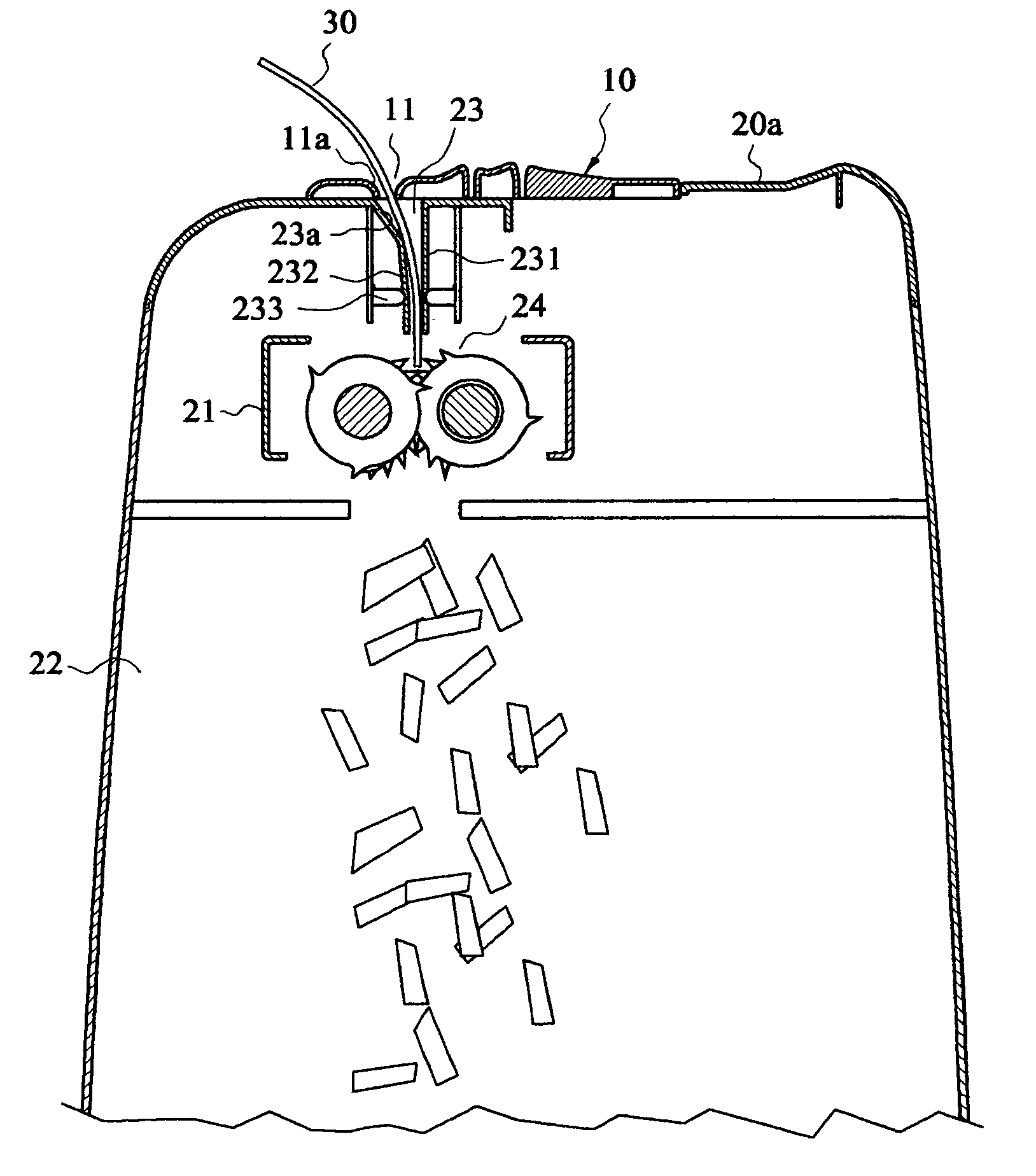
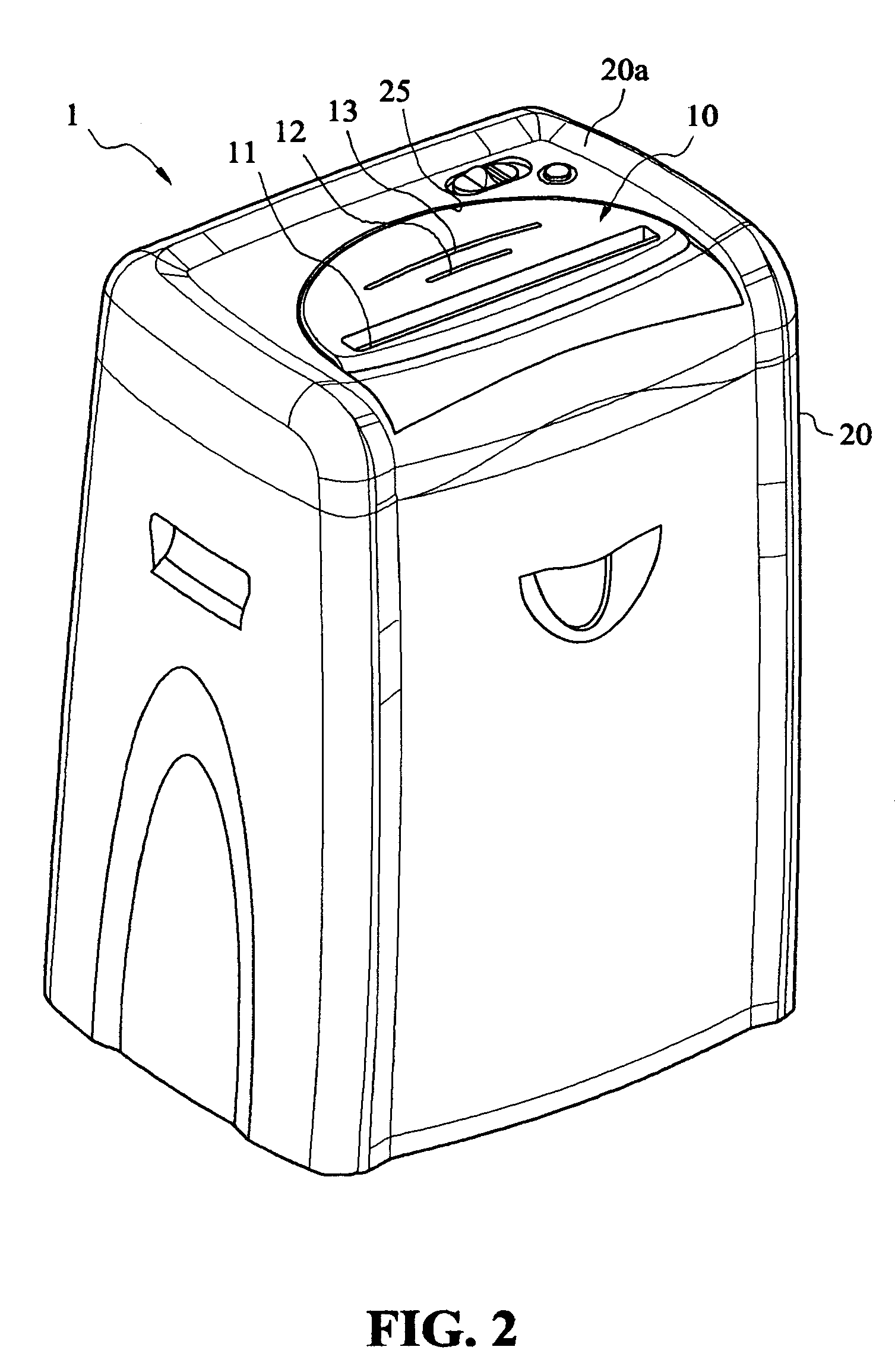
[0023]Referring to FIGS. 2, 3 and 4, a sliding panel structure 10 of a multifunctional paper shredder in accordance with the present invention relates to a paper shredder 1, comprising: a housing 20, having a top panel 20a to define an interior space, an installing section 21 at the top section of the interior space, and an accommodating space 22 at the bottom section. The top panel 20a of the housing 20 forms a semicircular accommodating space 25, and a feeding slot 23 is disposed on the accommodating section 25. A pair of actuating elements 24 respectively installs a knife and is fixed on the installing section 21 constit...


PUM


Abstract

Disclosed is a sliding panel structure of a multifunctional paper shredder, the paper shredder includes a housing having an interior space, an installing section at the top, an accommodating space at the bottom, and a feeding slot under the installing section. A pair of rolling blade wheels are disposed under the feeding slot which has a pressing wall surface extended vertically downward and aligned with the middle of the rolling blade wheels. An accommodating section is defined at the top of the housing, and a positioning section having at least one sliding groove is disposed at an inner side of the accommodating section. A sliding panel, having a plurality of slots is slidably installed in the accommodating section, having a positioning pin disposed in the positioning section correspondingly, and at least one slide pin embedded into the sliding groove for guiding the movement of the sliding panel.

Description

BACKGROUND OF THE INVENTION[0001]1. Field of the Invention[0002]The present invention relates to a sliding panel structure of a multifunctional paper shredder, and more particularly to a sliding panel design having a plurality of slots for receiving and scrapping paper of different materials, credit cards, and compact discs by selectively putting the paper, credit cards and compact discs into the specially designed slots.[0003]2. Description of the Related Art[0004]A paper shredder may be used to shred abandoned documents and papers to prevent disclosing confidential information or trade secrets, and the paper shredder is used extensively in industry and commerce. A conventional paper shredder as shown in FIGS. 1a and 1b and disclosed in the R.O.C. Utility Model Publication 551221 entitled “Two-way paper shredder” comprises: a housing 10 having a first and a second paper inlets 11, 13 at the top and the lateral side of the housing 10 respectively, a first and a second passages 12, 1...

Claims


Application Information

Patent Timeline
Patent Type & Authority Patents(United States)
IPC IPC(8): B02C18/22
CPCB02C18/0007B02C18/2291B02C2018/0015B02C2018/0046
Inventor CHEN, PAI-HSIEN
Owner AURORA GLOBAL INVESTMENT
Why Eureka
Try Eureka