Ball screw device

A rolling element and lead screw technology, applied in transmissions, belts/chains/gears, mechanical equipment, etc., can solve the problems of inability to balls, large number of parts, and high production costs

Inactive Publication Date: 2015-10-14
THK CO LTD
View PDF1 Cites 0 Cited by
  • Summary
  • Abstract
  • Description
  • Claims
  • Application Information

AI Technical Summary

Problems solved by technology

[0007] The rolling direction of the balls rolling on the peripheral surface of the screw shaft collides with the insert and changes abruptly to the radial direction, so the balls cannot circulate smoothly
Moreover, since the circulation part is composed of a return pipe and a pair of inserts installed at both ends in the length direction of the return pipe, the number of parts is large and the production cost is high
[0008] That is to say, in the above-mentioned insert-type circulation method, although the integral circle circulation of the ball can be realized, there is a problem of poor practicability in the smooth circulation of the ball and the manufacture of circulation components.

Method used


Image

  • Ball screw device
  • Ball screw device
  • Ball screw device

Examples


Embodiment Construction

[0079] Hereinafter, the structure and function of each part of the present invention will be described in detail with reference to the drawings. In addition, in the following description, the same code|symbol is attached|subjected to the same or a corresponding member or structure, and a repeated description is abbreviate|omitted.

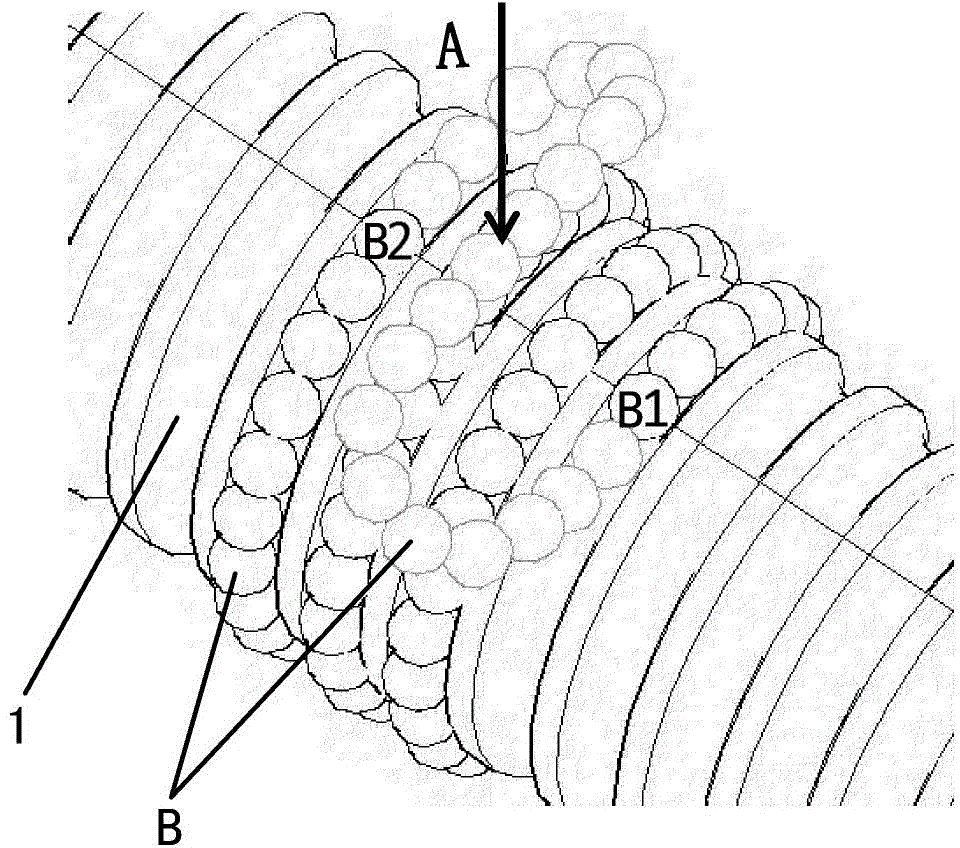
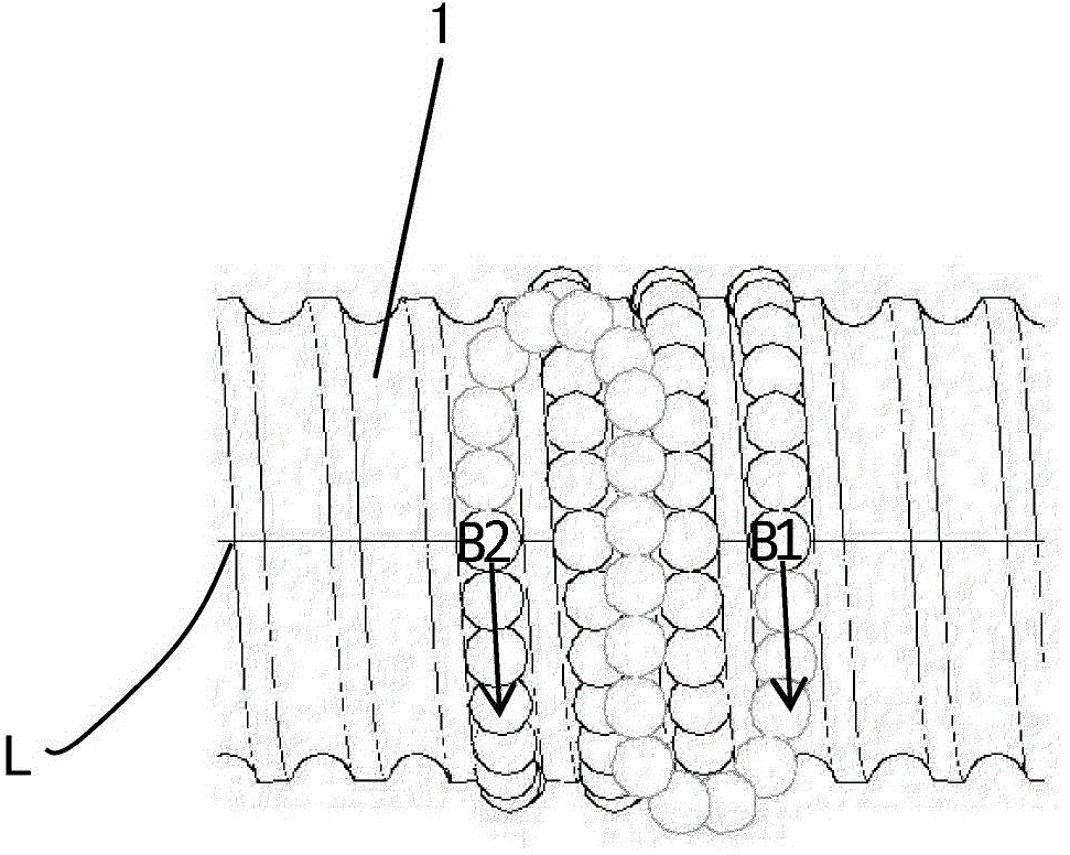
[0080] figure 1 It is a perspective view showing a ball circulation path in a state where a nut is omitted and only a screw shaft is shown in a ball screw as a rolling element screw device. figure 2 is along figure 1 A direction observation in figure 1 The obtained top view of the ball circulation path of one embodiment.

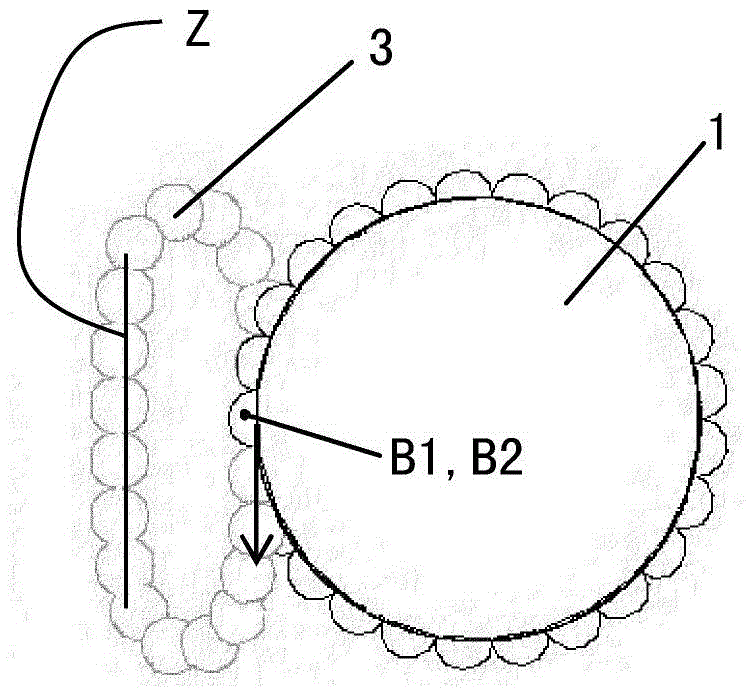
[0081] In the present invention, as shown in the description of the background technology of the present invention, in the ball screw, in order to make the ball B move between the screw shaft 1 and the nut 2 (see Figure 4 ), while the nut 2 is provided with a ball circulation path 3 for circulating the ball B rolling betwee...


PUM


Abstract

The invention provides a ball screw device. The ball screw device comprises a screw shaft, a nut, a plurality of balls and a circulating member, wherein a spiral ball rolling groove is formed in the outer peripheral surface of the screw shaft; a spiral loaded ball rolling groove opposite to the ball rolling groove of the screw shaft is formed in the inner peripheral surface of the screw; the balls are located between the ball rolling groove of the screw shaft and the loaded ball rolling groove of the screw; and the circulating member is assembled on the screw, provided with a ball circulating path which enables the balls between the ball rolling groove and the loaded ball rolling groove to circulate, and also provided with a pair of guiding parts used for guiding the balls in the tangential direction of the ball rolling groove of the screw shaft and a direction changing part arranged between the pair of guiding parts and used for changing the rolling direction of the balls, and observation is carried out along the axis of the screw shaft, at least the part, close to the loaded ball rolling groove, of the pair of guiding parts are on the same tangent line relative to the ball rolling groove of the screw shaft. Therefore, the balls can be enabled to roll smoothly to realize high-speed rotation of the ball screw device, besides, the loading capacity of the ball screw device is improved, and the loading balance of the balls is favorable.

Description

technical field [0001] The present invention relates to a rolling element screw device, in particular to a circulation member for circulating rolling elements in the rolling element screw device. Background technique [0002] The ball screw unit, one of the rolling element screw units, is a mechanical element that converts rotary motion into linear motion. In order to reduce the friction when the screw shaft rotates relative to the nut, the balls roll between the ball rolling groove on the peripheral surface of the screw shaft and the loaded ball rolling groove on the inner peripheral surface of the nut facing it. A plurality of balls capable of rolling motion are arranged in the path. [0003] In order to circulate the balls between the screw shaft and the nut, a ball circulation path is provided on the nut. The balls rolling between the screw shaft and the nut are scooped up into the ball circulation path after rolling to one end of the loaded ball rolling groove of the ...

Claims


Application Information

Patent Timeline
Patent Type & Authority Applications(China)
IPC IPC(8): F16H25/22
CPCF16H25/2214
Inventor 费珊珊张兴福余波于兴家何新玲
Owner THK CO LTD
Why Eureka
Try Eureka