Optical fiber connector assembly

An optical fiber connector and connector technology, which is applied in optical components, light guides, optics, etc., can solve the problems of not easy bending of optical cables, inconvenient laying of optical cables, twisting and knotting of optical cables, etc., and achieve the effect of improving connection strength.

Inactive Publication Date: 2015-10-14
TYCO ELECTRONICS (SHANGHAI) CO LTD
View PDF6 Cites 6 Cited by
  • Summary
  • Abstract
  • Description
  • Claims
  • Application Information

AI Technical Summary

Problems solved by technology

[0007] The aforementioned connection method 3 guarantees the bearing force of the optical cable by implanting a strengthening element in the optical cable and fixing the strengthening element. This solution can withstand a relatively large tensile force, for example, several hundred Newtons, but it has defects. In, making the optical cable hard, the optical cable is not easy to bend, and cannot be bent arbitrarily within the range of 360 degrees. In addition, in the laying of very long optical cables, the optical cables are prone to twisting and knotting, which causes inconvenience to the laying of optical cables.

Method used


Image

  • Optical fiber connector assembly
  • Optical fiber connector assembly
  • Optical fiber connector assembly

Examples


Embodiment Construction

[0038] The technical solutions of the present invention will be further specifically described below through the embodiments and in conjunction with the accompanying drawings. In the specification, the same or similar reference numerals designate the same or similar components. The following description of the embodiments of the present invention with reference to the accompanying drawings is intended to explain the general inventive concept of the present invention, but should not be construed as a limitation of the present invention.

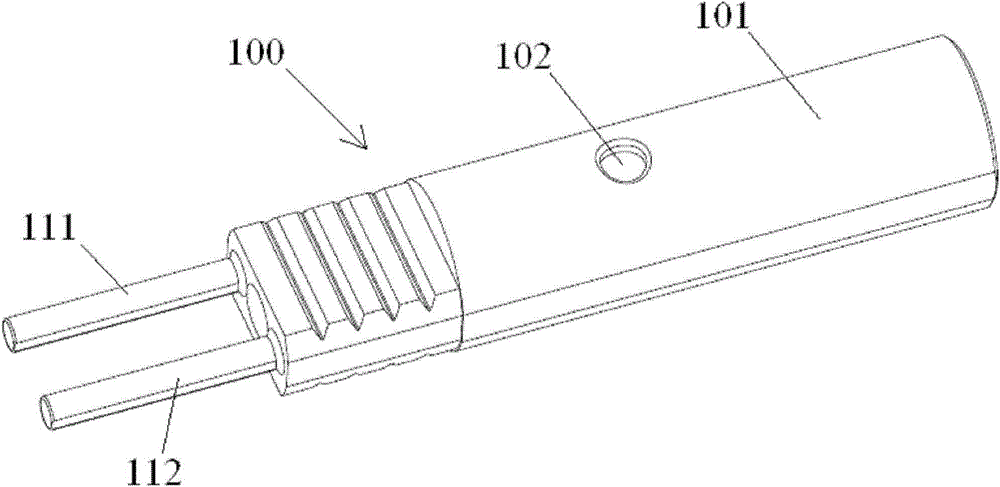
[0039] According to the concept of the present invention, an optical fiber connector assembly is provided, including: a connector; an optical cable 200, a reinforcing element layer 202 is arranged between the protective sleeve 203 of the optical fiber 204 of the optical cable 200 and the outer sheath layer 201; The transition piece 100 and the intermediate transition piece 100 are respectively glued to the reinforcing element layer 202 of the ...


PUM


Abstract

The invention discloses an optical fiber connector assembly comprising a connector, a cable and an intermediate transfer member. A reinforced element layer is arranged between the protective sleeve pipe and outer sheath layer of the optical fiber of the cable. The intermediate transfer member is respectively adhered and connected with the reinforced element layer and the body of the connector, and thus the cable and the connector are connected together. Compared with the prior art, the connection strength between the cable and the connector is improved. In addition, since the reinforced element layer is a flexible thin layer which is uniformly distributed around the optical fiber protective sleeve pipe, the hardness of the cable is not increased, the cable can be bent, and the twisting and knotting phenomena of a cable in laying a long cable are prevented.

Description

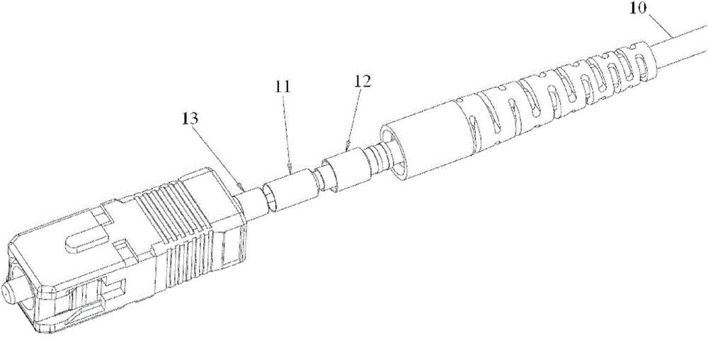
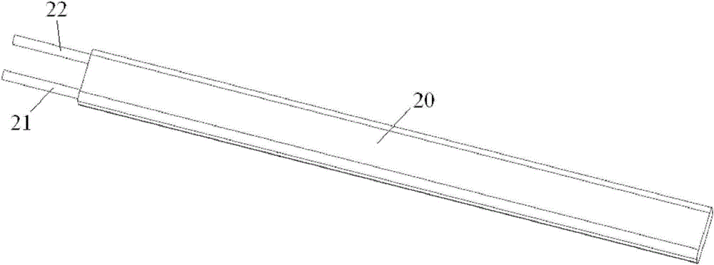
technical field [0001] The invention relates to an optical fiber connector assembly. Background technique [0002] In the prior art, there are three main methods of mechanical connection between optical fiber connectors and optical cables: [0003] 1. If figure 1 As shown, the metal crimping ring 12 is used to crimp the Kevlar 11 in the optical cable 10 to fix the optical cable 10 on the base 13. The structure and crimping method of this optical cable determine that the tensile force of the connector and the optical cable is limited; [0004] 2. Directly crimp the outer sheath of the optical cable to fix the optical cable; [0005] 3. If figure 2 As shown, the strengthening elements 21 and 22 are directly implanted in the optical cable 20, and the optical cable 20 is fixed by fixing the strengthening elements 21 and 22. [0006] The aforementioned connection mode 1 and connection mode 2 are suitable for bearing a relatively small tensile force, for example, tens of Newt...

Claims


Application Information

Patent Timeline
Patent Type & Authority Applications(China)
IPC IPC(8): G02B6/38G02B6/44
CPCG02B6/3628G02B6/3833G02B6/4432
Inventor 柴雄良范文勇
Owner TYCO ELECTRONICS (SHANGHAI) CO LTD
Why Eureka
Try Eureka