

Fiber Connector Assemblies
An optical fiber connector and connector technology, which is applied in optical components, light guides, optics, etc., can solve the problems that the optical cable is not easy to bend, the optical cable is twisted and knotted, and the optical cable becomes hard, and the effect of improving the connection strength is achieved.
- Summary
- Abstract
- Description
- Claims
- Application Information
AI Technical Summary
Problems solved by technology
Method used
Image

Examples
Embodiment Construction
[0038] The technical solutions of the present invention will be further specifically described below through the embodiments and in conjunction with the accompanying drawings. In the specification, the same or similar reference numerals designate the same or similar components. The following description of the embodiments of the present invention with reference to the accompanying drawings is intended to explain the general inventive concept of the present invention, but should not be construed as a limitation of the present invention.
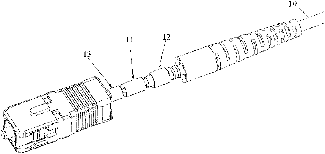
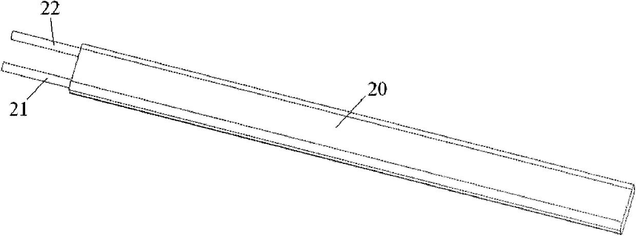
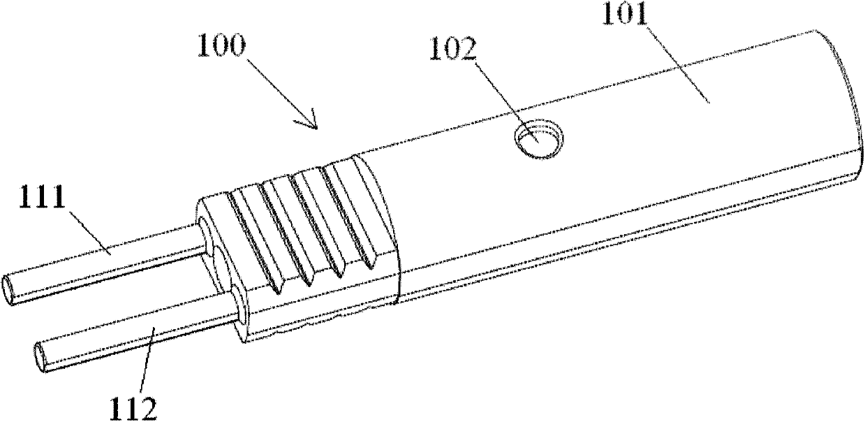
[0039] According to the concept of the present invention, an optical fiber connector assembly is provided, including: a connector; an optical cable 200, a reinforcing element layer 202 is arranged between the protective sleeve 203 of the optical fiber 204 of the optical cable 200 and the outer sheath layer 201; The transition piece 100 and the intermediate transition piece 100 are respectively glued to the reinforcing element layer 202 of the ...
PUM
 Abstract
Description
Claims
Application Information