
nfc antenna with metal back case

A metal back shell and antenna technology, applied in the field of communication, can solve problems such as complex process and unsightly structure, and achieve the effect of simple processing process, superior performance and guaranteed integrity

Active Publication Date: 2018-07-10
SHENZHEN SUNWAY COMM
View PDF4 Cites 0 Cited by
  • Summary
  • Abstract
  • Description
  • Claims
  • Application Information

AI Technical Summary

Problems solved by technology

However, the two slits in this plan cut the complete metal back shell into two parts, the structure is very unsightly, and the two parts of the metal back shell need to be processed separately, and the process is complicated

Method used


Image

  • nfc antenna with metal back case
  • nfc antenna with metal back case
  • nfc antenna with metal back case

Examples


Embodiment 1

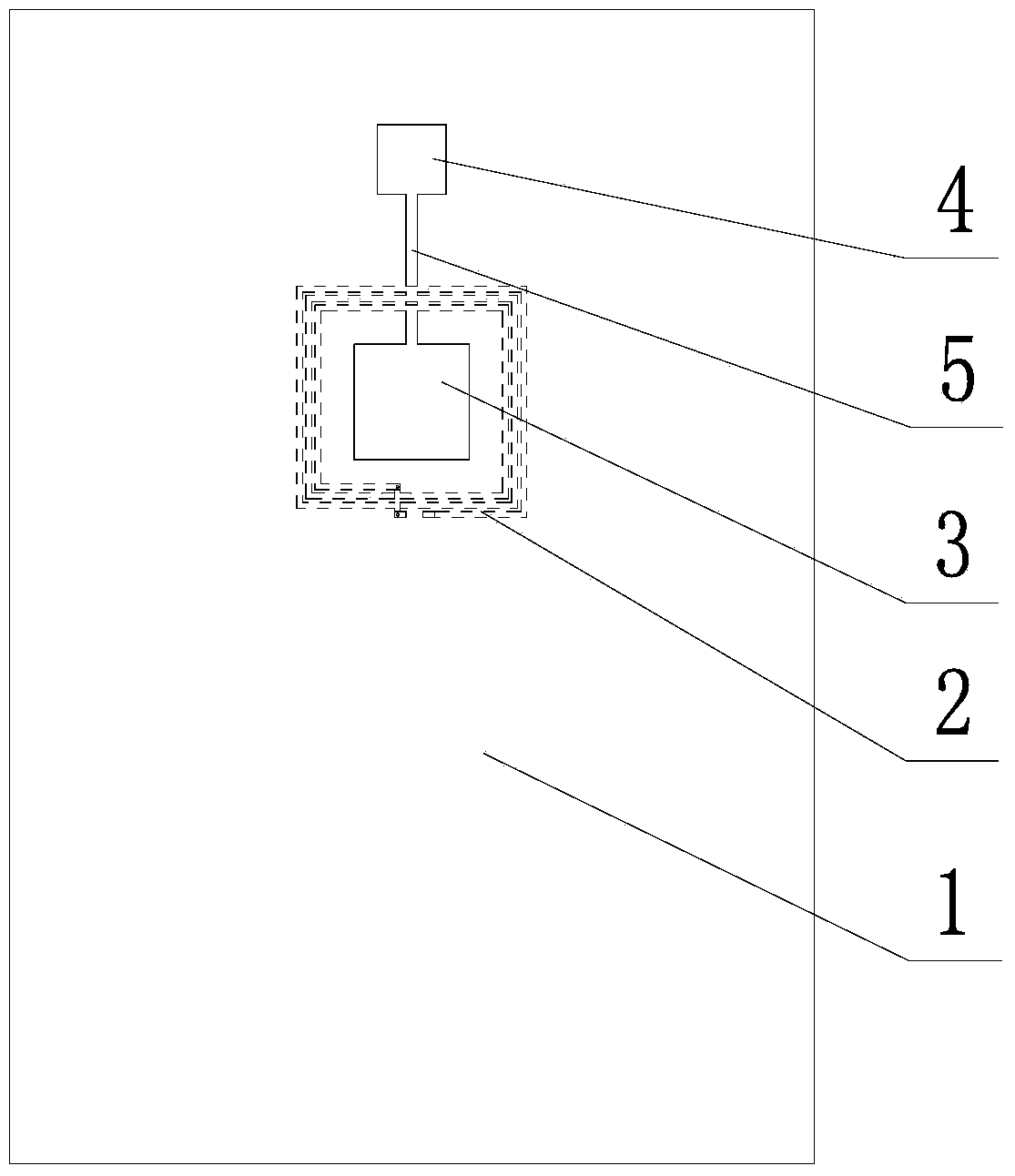
[0027] Please refer to figure 2 , the first embodiment of the present invention is: an NFC antenna with a metal back shell, including a metal back shell 1 and an antenna coil 2, the metal back shell is an all-metal back shell, and the metal back shell includes a first The hole 3 and the second through hole 4, the first through hole 3 is shown in the figure below the second through hole 4, in fact, the two can also exchange positions, and even the two can be in a left-right positional relationship; the first through-hole 3 is located below the second through-hole 4. The through hole and the second through hole can be used to install fingerprint recognition module, camera module, flash module or other sensor modules respectively; the antenna coil 2 is located inside the metal back shell, that is, the side where the battery, mobile phone chip, etc. are installed, and surrounds the The first through hole 3 is provided, and the metal back shell is further provided with a first slo...

Embodiment 2

[0031] Please refer to Figure 4 , the second embodiment of the present invention further increases through holes on the basis of the first embodiment, such as 3, 4, and 5 through holes, and the plurality of through holes can be connected through multiple slots; the NFC antenna coil can be set around any via, but usually choose the largest via for better performance. Figure 4 The case of three through holes is shown, the three through holes can be a combination of fingerprint identification through holes, camera through holes and flash through holes, and a second gap 7 can be opened between the second through hole 4 and the third through hole 6 . It should be pointed out here that the first slit 5 in the up-down direction must be opened, and the second slit 7 in the left-right direction may not be opened. However, compared with the case without the second slot 7, the performance of the NFC antenna will be enhanced with the second slot 7. Figure 5 The simulation result of ...


PUM


Abstract

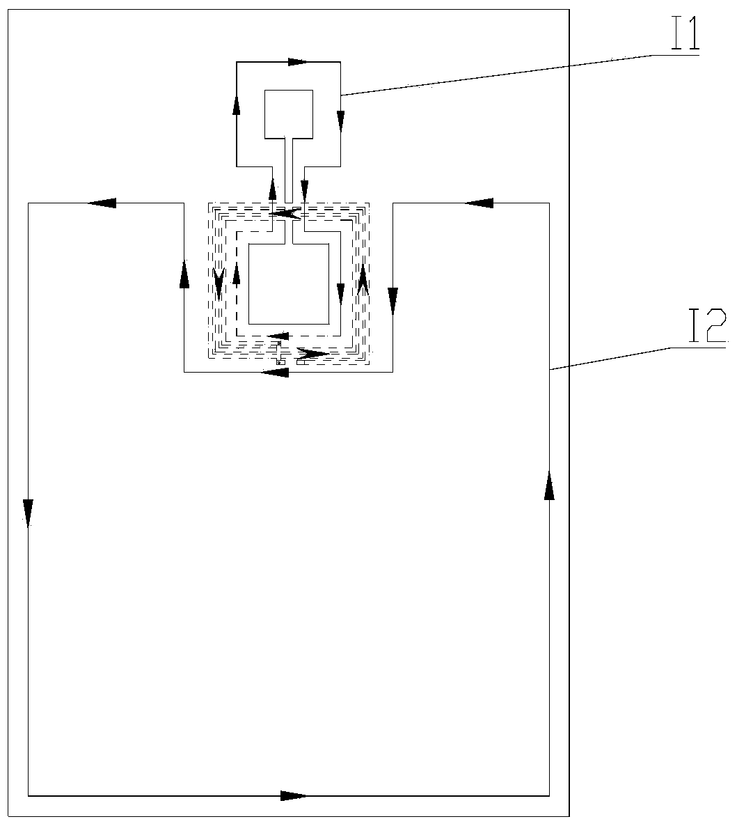
The invention discloses an NFC antenna with a metal back shell, which comprises a metal back shell and an antenna coil, the metal back shell includes a first through hole and a second through hole, and the antenna coil is located inside the metal back shell , and arranged around the first through hole, the metal rear shell is further provided with a first slit, and the first slit connects the first through hole and the second through hole. Use the gap to connect the through hole to change the distribution of the eddy current flow and at the same time achieve the effect of eliminating the shielding effect of the metal back shell on the NFC antenna, and apply the eddy current on the metal shell in the same direction as the antenna itself to enhance the performance of the antenna. The invention has a beautiful structure , The production process is simple, and the performance is superior.

Description

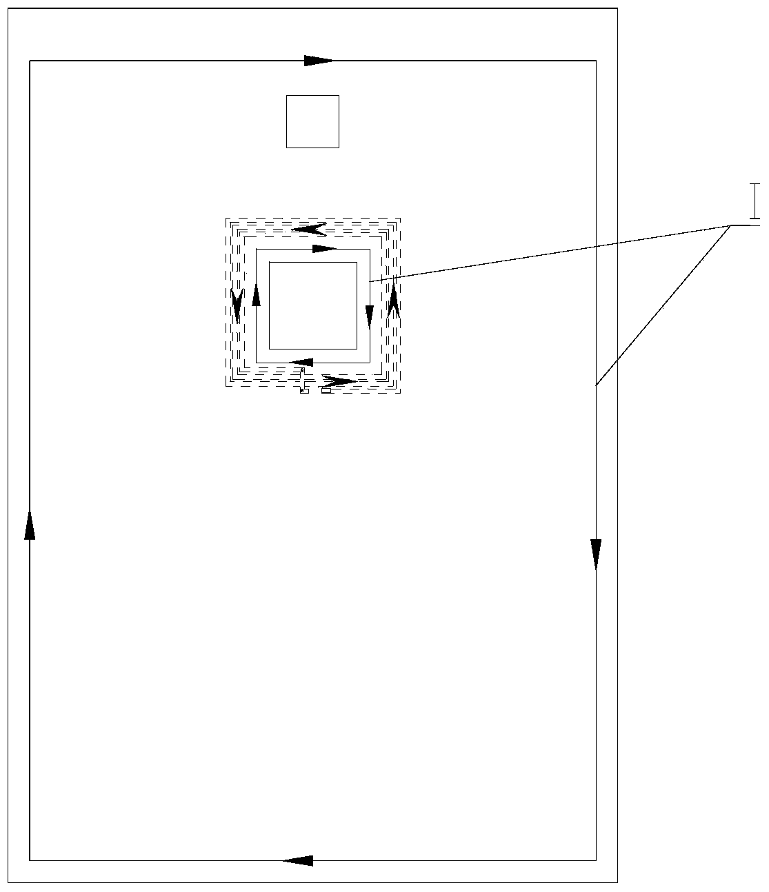
technical field [0001] The invention relates to the field of communications, in particular to an NFC antenna with a metal back shell. Background technique [0002] With the development of the communication function of mobile devices at this stage, the NFC antenna has gradually become the object favored by the majority of customers, so the research on the design of the NFC antenna has been paid more and more attention. Generally, the NFC antenna is placed on the battery, and a piece of ferrite can be added to obtain better performance. Recently, with the favor of consumers, mobile devices with metal back shells have become popular, which brings greater difficulty to the design of NFC antennas. like figure 1 As shown, because the NFC antenna is placed directly behind the metal casing, an eddy current I that is completely reversed to the current of the NFC antenna is generated on the metal back casing, and the antenna cannot be detected due to this completely reversed eddy cu...

Claims


Application Information

Patent Timeline
Patent Type & Authority Patents(China)
IPC IPC(8): H01Q1/36H01Q1/24H01Q7/00
Inventor 陈浩赵安平徐雨王翟谷媛牛宝星尹鸿焰
Owner SHENZHEN SUNWAY COMM
Learn More