Method and apparatus for operating shear

A shearing machine, technology on the operating side, applied in the direction of knives for shearing machines, equipment for shearing machines, devices for cutting with nibbling action

Inactive Publication Date: 2015-10-14
PRIMETALS TECH
View PDF10 Cites 2 Cited by
  • Summary
  • Abstract
  • Description
  • Claims
  • Application Information

AI Technical Summary

Problems solved by technology

[0004] For some users of the clipboard, the edge notch and associated slight protrusion at the point of discontinuity may be unacceptable

Method used


Image

  • Method and apparatus for operating shear
  • Method and apparatus for operating shear
  • Method and apparatus for operating shear

Examples


Embodiment Construction

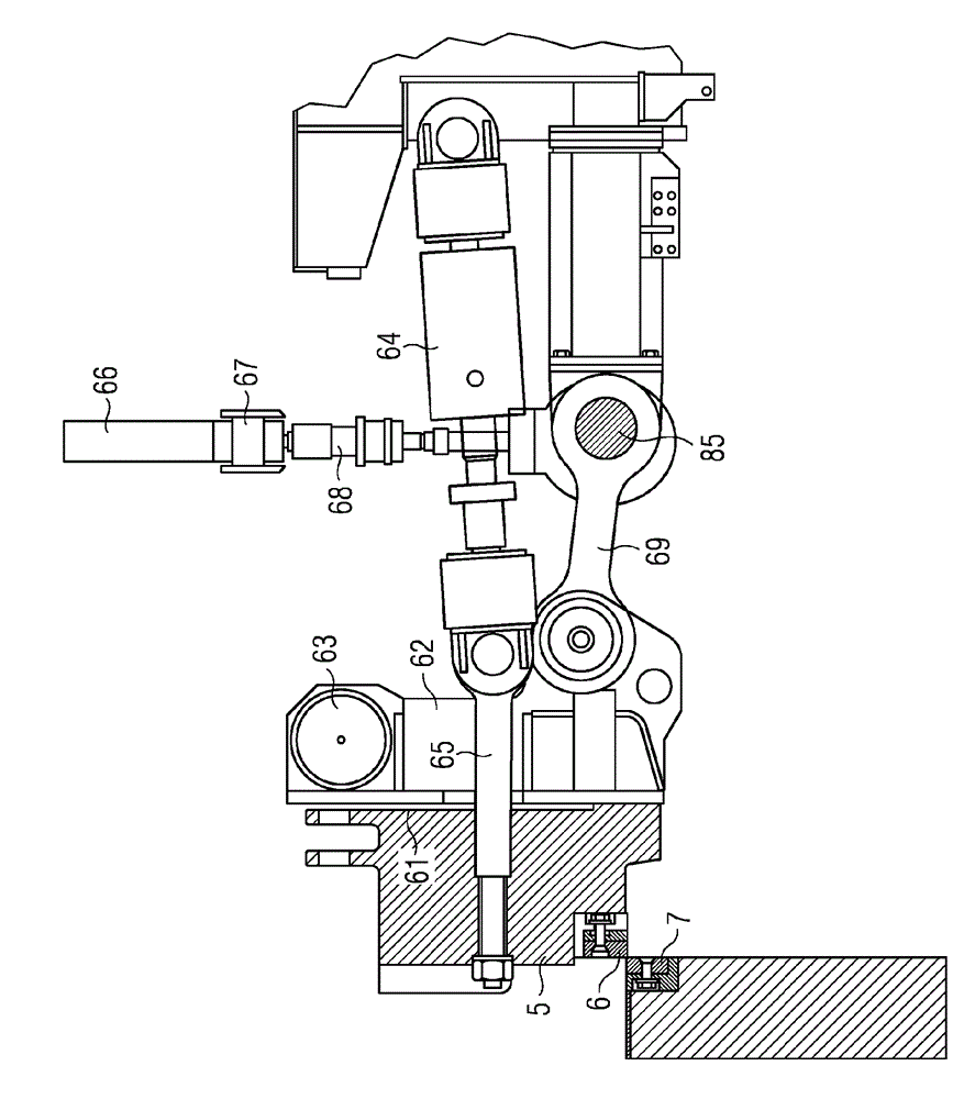
[0054] The present invention solves the problem of discontinuous defects in side trimming or slitting shears. While thinner sheet metal (up to about 20mm to 25mm thick) can be cut with rotary shears, most shears for cutting thicker sheet metal (up to about 50mm to 60mm thick) are Rolling blade type. One blade (usually the upper blade) is curved, while the other blade (usually the lower blade) is straight, and the upper blade performs a rolling type cutting action. Most commonly, a rolling type cutting action is produced by a double crank mechanism. exist figure 1A typical mechanism is illustrated in . The cranks 1 , 2 are connected by rods 3 , 4 to a top beam 5 to which a curved upper blade 6 is attached. A straight lower blade 7 is attached to the shearer housing 8 . Rotation of the cranks 1, 2 causes the upper blade 6 to move down from its uppermost open position until it touches the plate and performs a rolling type cut. At the end of the cut, continued rotation of th...


PUM


Abstract

A method of operating a side trim or slitting shear to shear a full length of a material (10) to be sheared is described. The full length comprises a plurality of cutting lengths and the shear comprises a first blade (6) and a second blade (7). The methodcomprises determining parameters of a material to be sheared and storing the determined parameters. In one cutting cycle, the method comprises cutting a single cutting length (14) of the material; carrying out a series of cutting cycles to cut the full length of the material; and in a control system at least once in the series of cutting cycles using the determined parameters to control adjustment of the gap (H) between the first and second blades in a cutting phase in a cutting cycle. The angle between the blades may also be adjusted 

Description

technical field [0001] The present invention relates to a method for operating a shear for shearing sheet metal and related equipment. In particular, it concerns shears for side trimming and slitting sheet metal. Background technique [0002] Shears used for trimming and slitting steel plate are usually of the rolling blade type. This type of shear operates using cyclic steps. In this case, the blade of the shear is shorter than the length required to cut the full length of the board. Thus, the shearing operation is performed in a series of cutting cycles, each cut slightly shorter than the length of the blade and much shorter than the full length of the plate. [0003] Intermittent defects are sometimes produced in the sheared edge as a result of the cyclic step operation of the shearing machine. This discontinuity takes the form of a notch at a location on the cutting edge of the plate corresponding to where each shear cycle ends and the next begins. [0004] For some...

Claims


Application Information

Patent Timeline
Patent Type & Authority Applications(China)
IPC IPC(8): B23D31/04B23D35/00
CPCB23D27/00B23D15/12B23D35/005B23D15/04
Inventor D.斯拓内里弗
Owner PRIMETALS TECH
Why Eureka
Try Eureka