Connection device of thin-wall flexible tube and connection method thereof

A technology for hose connection and connection device, which is applied in the direction of hose connection device, pipe/pipe joint/pipe fitting, mechanical equipment, etc., and can solve the problems of complex pasting process, gaps, and limited clamping effect.

Inactive Publication Date: 2015-10-14
GUANGZHOU AIRGOAL SPORTS EQUIP CO LTD
View PDF4 Cites 8 Cited by
  • Summary
  • Abstract
  • Description
  • Claims
  • Application Information

AI Technical Summary

Problems solved by technology

However, the glue is prone to aging, or there may be gaps when pasting, so using glue to connect is prone to gas or liquid leakage, and the pasting process is more complicated; and using clips for fixing, such as hose The thickness of the tube wall is thin, so when it is difficult to clamp, the tube wall of the hose is not deformed much, the clamping effect is limited, and gas or liquid leakage is also prone to occur.

Method used


Image

  • Connection device of thin-wall flexible tube and connection method thereof
  • Connection device of thin-wall flexible tube and connection method thereof
  • Connection device of thin-wall flexible tube and connection method thereof

Examples


Embodiment 1

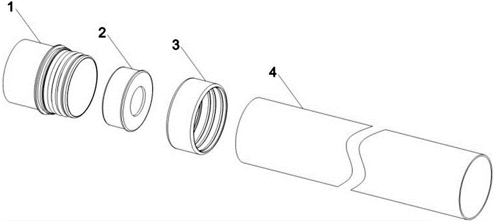
[0044] Embodiment one: refer to figure 1 It is an exploded view of the structure of this embodiment. The hose connection device is composed of a joint 1, a fixed sleeve 2, an outer ring 3 and a hose 4, and the specific connection steps are as follows:

[0045] Step 1: If Figure 5 As shown, before processing, the outer ring 3 is immersed in 100°C water, boiled for 10 hours to make it fully absorb water and swell and become soft, and then put it on the outside of the hose 4;

[0046] Step 2: If Figure 7 As shown, put the hose 4 into the joint, so that the end of the hose 4 is close to the position of the second outer side 14 of the limit baffle;

[0047] Step 3: If Figure 8 As shown, use the processing equipment to push the outer ring 3 to the position of the limit baffle 11;

[0048] Step 4: If Figure 9As shown, after the outer ring enters, it uses the plastic elastic to naturally shrink and clamp the hose, and the inverted tooth that is staggered from the...

Embodiment 2

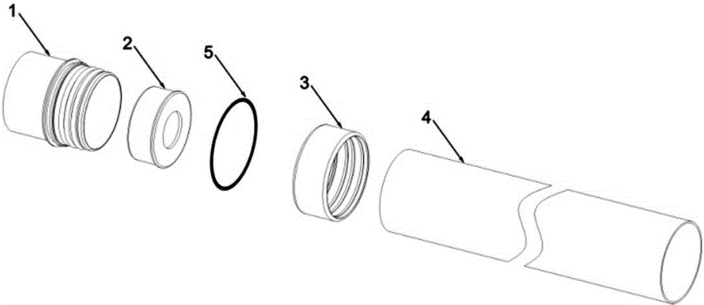
[0050] Embodiment two: refer to figure 2 It is an exploded view of the structure of this embodiment. The hose connection device is composed of a joint 1, a solid sleeve 2, an outer ring 3, a hose 4 and a sealing ring 5, and the specific connection steps are as follows:

[0051] Step 1: If Image 6 As shown, before processing, immerse the outer ring 3 in water at 100°C and cook for 12 hours to make it fully absorb water and swell and become soft. sealing ring 5;

[0052] Step 2: If Figure 7 As shown, put the hose 4 into the joint, so that the end of the hose 4 is close to the position of the second outer side 14 of the limit baffle;

[0053] Step 3: If Figure 8 As shown, use the processing equipment to push the outer ring 3 to the position of the limit baffle 11;

[0054] Step 4: If Figure 9 As shown, after the outer ring enters, the plastic elastic is used to naturally shrink and clamp the hose, and the inverted tooth that is staggered from the joint cla...

Embodiment 3

[0058] Embodiment three: refer to Figure 10 This connection device is applied to the structure diagram of the goal. The connecting part of the two posts of the goal adopts the connection device introduced by the present invention, and the goal post adopts the flexible pipe introduced by the present invention. Inflate the valve so that the hose is full, giving Figure 10 The goal shown in the figure; when not in use, release the gas in the hose and put it in a bag after compression, which is light in weight, does not take up space and is easy to carry. Since the doorpost adopts an inflatable hose, it has a cushioning effect when a person bumps into it and will not be injured.


PUM


Abstract

The invention provides a connection device of a thin-wall flexible tube and a connection method thereof. The connection device includes a joint, a firm sleeve built in the joint and used for supporting the joint, and an outer ring sleeves the flexible tube so as to compress the flexible tube onto the joint. The connection device is characterized in that an outer wall surface of the joint is provided with in turn: a limiting baffle plate 1, a groove, two inner sides of a limiting baffle plate, and two or more pawls which are arranged. With the direction of the pawls, it is convenient for the flexible tube being inserted while not exiting. The outer ring is made from plastic material which expands and becomes flexible after water absorption. The inner wall of the outer ring is provided with two or more pawls with the direction opposite to that of the joint pawls. During a connection state, the position of the pawls is staggered with that of the joint pawls. The connection device is fully made of plastic. The sealing connection to the flexible tube and the joint is realized by using the character that the plastic outer ring material expands and becomes flexible after water absorption and elastically and naturally contracts, and the special size design that a gap of the outer ring and the joint is less than the wall thickness of the flexible tube.

Description

technical field [0001] The invention relates to a connecting device and a connecting method thereof, in particular to a connecting device and a connecting method of a hose. Background technique [0002] At present, hoses and hoses, hoses and hard pipes are often connected by connecting devices. The connection method between the hose and the connecting device is generally to paste the hose on the joint of the connecting device with glue, and then tighten the metal or plastic collar on the outside; or the hose is sleeved on the joint After it is installed, it is clamped with a clamp to compress the hose so that the wall of the hose is deformed to a certain extent, thereby fixing the hose to the joint. However, the glue is prone to aging, or there may be gaps when pasting, so using glue to connect is prone to gas or liquid leakage, and the pasting process is more complicated; and using clips for fixing, such as hose The thickness of the tube wall is thin, and when it is dif...

Claims


Application Information

Patent Timeline
Patent Type & Authority Applications(China)
IPC IPC(8): F16L33/207F16L33/18
CPCF16L33/00F16L33/22F16L33/2071F16L33/18F16L33/2073
Inventor 梁广仁
Owner GUANGZHOU AIRGOAL SPORTS EQUIP CO LTD
Why Eureka
Try Eureka