GIC measurement method and device for buried oil and gas pipelines and cathodic protection devices

A technology for cathodic protection and oil and gas pipelines, applied in the field of GIC monitoring of buried oil and gas pipelines, can solve problems such as corrosion, poor measurement accuracy, and large errors, and achieve the effect of avoiding major accidents

Inactive Publication Date: 2017-10-10
CHINA UNIV OF PETROLEUM (BEIJING)
View PDF3 Cites 0 Cited by
  • Summary
  • Abstract
  • Description
  • Claims
  • Application Information

AI Technical Summary

Problems solved by technology

The pipe ground potential PSP will exceed the range of the national cathodic protection standard, thus making the traditional cathodic protection out of control. Therefore, geomagnetic storms will accelerate the corrosion of metal pipes
Second, for pipelines with localized corrosion, the higher the pipe-to-ground potential PSP, the greater the current flowing into or out of the existing localized corrosion, resulting in more serious corrosion and even arcing, which leads to sudden oil and gas leakage and explosions in the pipeline. ACCIDENT
Third, for equipment such as cathodic protection devices, instruments and sensors connected to pipelines with grounding points, the GIC current will affect their normal operation and even burn them through their grounding points
Since the resistance on the pipeline cannot be obtained accurately, the error is large
[0011] Therefore, the indirect method of measuring the pipeline GIC without using a current transformer needs information such as the pipeline and its environmental background parameters, and is also affected by the background electromagnetic field, so the measurement accuracy is poor

Method used


Image

  • GIC measurement method and device for buried oil and gas pipelines and cathodic protection devices
  • GIC measurement method and device for buried oil and gas pipelines and cathodic protection devices
  • GIC measurement method and device for buried oil and gas pipelines and cathodic protection devices

Examples


Embodiment Construction

[0045] The present invention will be described in detail below in conjunction with the accompanying drawings and specific embodiments. The following description is only for demonstration and explanation, and does not limit the present invention in any form.

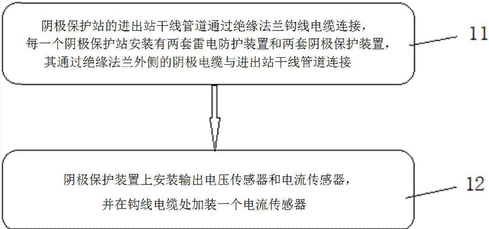
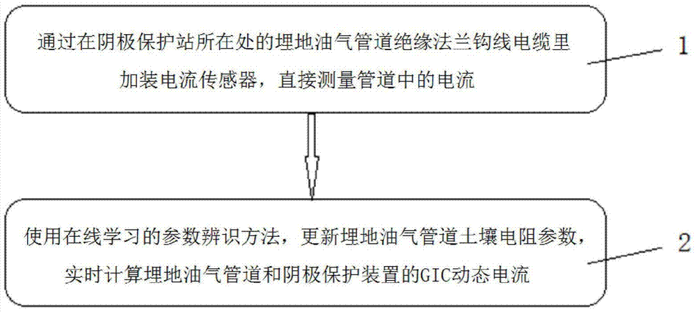
[0046] Such as figure 1 As shown, the GIC measurement method for buried oil and gas pipelines and cathodic protection devices includes steps 1 and 2:

[0047] Step 1. Directly measure the current in the buried oil and gas pipeline by installing a current sensor in the insulated flange hook cable of the buried oil and gas pipeline where the cathodic protection station is located;

[0048] Step 2. Using online learning parameter identification methods, update the soil resistance parameters of buried oil and gas pipelines, and calculate the GIC dynamic current of buried oil and gas pipelines and cathodic protection devices in real time.

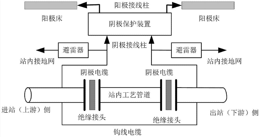
[0049] Generally, the in-station process pipeline of the gas pipeline pigging station (cathodic ...


PUM


Abstract

The invention discloses a measuring method and device for a buried oil-gas pipeline and a cathodic protection device. The GIC measuring method comprises the following steps: a current sensor is additionally mounted in an insulated-flange hook-line cable of the buried oil-gas pipeline so as to measure electric currents in the buried oil-gas pipeline; a current and voltage sensor is mounted in the cathodic protection device so as to measure electric currents and voltages in the cathodic protection device; a parameter identification method for on-line study is used to update the soil resistance parameters of the buried oil-gas pipeline, and calculate the GIC dynamic current of the buried oil-gas pipeline and the GIC dynamic current of the cathodic protection device in real time. Through the adoption of the measuring method disclosed by the invention, the problems in the indirect measurement of GIC and the dynamic current of the cathodic protection device are effectively solved; the GIC of the buried oil-gas pipeline at a cathodic protection station, and the GIC of the cathodic protection device at the cathodic protection station can be accurately monitored; the influence of a geomagnetic storm on the buried oil-gas pipeline can be correctly evaluated, and defensive measures can be taken in time to avoid major accidents.

Description

Technical field [0001] The invention relates to the technical field of GIC monitoring of buried oil and gas pipelines, in particular to a GIC measurement method and device for buried oil and gas pipelines and cathodic protection devices. Background technique [0002] With the rapid development of the national economy, the country's demand for oil and natural gas has been increasing year by year. There is no doubt that the rapid construction and development of buried oil and gas pipelines (hereinafter referred to as pipelines) have effectively guaranteed the country's energy supply and promoted economic development. However, at the same time, if the pipeline fails safely, it will have a serious impact on the operation of the national economy. If the pipeline leaks and perforates, causing fires, explosions or accidents, it will cause serious harm to people's lives, the environment and national property. Therefore, it should be strictly controlled in terms of design, construction a...

Claims


Application Information

Patent Timeline
Patent Type & Authority Patents(China)
IPC IPC(8): C23F13/22
Inventor 梁志珊赵耀峰夏鹏程生龙
Owner CHINA UNIV OF PETROLEUM (BEIJING)
Why Eureka
Try Eureka