Flight control method and device for unmanned aerial vehicle

A technology for unmanned aerial vehicles and flight control, which is applied in the field of aircraft and can solve problems such as unsatisfactory requirements

Inactive Publication Date: 2015-10-21
高域(北京)智能科技研究院有限公司
View PDF6 Cites 72 Cited by
  • Summary
  • Abstract
  • Description
  • Claims
  • Application Information

AI Technical Summary

Problems solved by technology

[0004] It can be seen that the existing aircraft flight control methods mainly focus on flight line control. In practice, in order to avoid the influence of unmanned aerial vehicles, control areas are usually set over specific areas (such as airports, military bases, etc.), and only controlling flight lines is often not enough. meet needs

Method used


Image

  • Flight control method and device for unmanned aerial vehicle
  • Flight control method and device for unmanned aerial vehicle
  • Flight control method and device for unmanned aerial vehicle

Examples


Embodiment 1

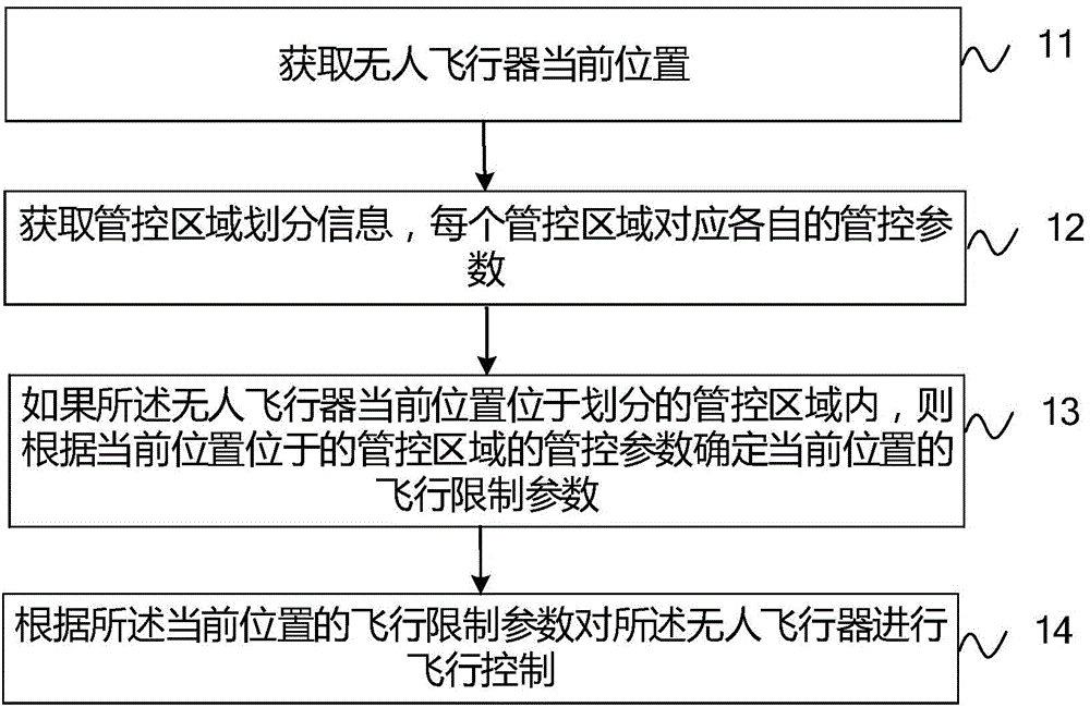
[0054] like figure 1 As shown, an embodiment of the present invention provides a flight control method for an unmanned aerial vehicle, including:

[0055] 11. Obtain the current position of the UAV.

[0056] Specifically, the embodiment of the present invention can obtain the current position of the UAV in various ways, and the embodiment of the present invention does not limit the manner of obtaining the current position of the UAV. For example, the location of the UAV is acquired in real time by a GPS module installed on the UAV, and the current location of the UAV is obtained, for example, according to the GPS signal combined with electronic map data.

[0057] 12. Obtain information on the division of control areas, and each control area corresponds to its own control parameters.

[0058] The control parameters include at least one of the following parameters: a maximum flight altitude, a minimum flight altitude, a maximum flight speed, and a minimum flight speed.

[005...

Embodiment 2

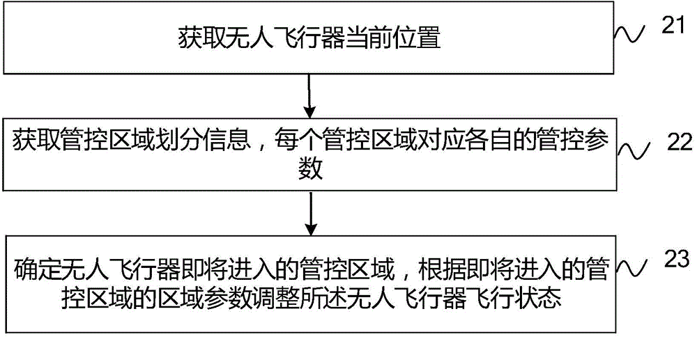
[0077] like figure 2 As shown, the present embodiment provides a method for controlling the flight of an unmanned aerial vehicle including:

[0078] 21. Obtain the current position of the UAV.

[0079] 22. Obtain the control area division information, and each control area corresponds to its own control parameters.

[0080] The above steps 21 and 22 can be implemented with reference to steps 11 and 12 in Embodiment 1, and details are not described here.

[0081] 23. Determine the control area that the unmanned aerial vehicle is about to enter, and adjust the flight state of the unmanned aerial vehicle according to the area parameters of the control area that is about to enter.

[0082] Wherein, the control parameters of the control area to be entered may include one or more of the maximum flight altitude, the minimum flight altitude, the maximum flight speed, and the minimum flight speed. For example, if the current flight altitude is less than the minimum flight altitude ...

Embodiment 3

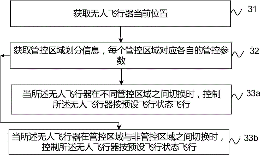
[0085] like image 3 As shown, the present embodiment provides a method for controlling the flight of an unmanned aerial vehicle including:

[0086] 31. Obtain the current position of the UAV.

[0087] 32. Obtain information on the division of control areas, and each control area corresponds to its own control parameters.

[0088] The above steps 31 and 32 can be implemented with reference to steps 11 and 12 in Embodiment 1, and details are not described here.

[0089] 33a. When the UAV switches between different control areas, control the UAV to fly in a preset flight state.

[0090] 33b. When the UAV is switched between a controlled area and a non-controlled area, control the UAV to fly in a preset flight state.

[0091] Wherein, the above-mentioned parameters set in the preset flight state include but are not limited to parameters such as flight altitude and flight speed.

[0092] The method of this embodiment switches between different areas, and the unmanned aerial ve...


PUM


Abstract

The invention provides a flight control method and a device for an unmanned aerial vehicle, and belongs to the field of aerial vehicles. The method comprises steps of obtaining the current position of the unmanned aerial vehicle; obtaining division information of control regions, wherein each of the control regions corresponds to a control parameter; determining the flight restriction parameter of the current position according to the control parameter of the control area where the current position is if the unmanned aerial vehicle is in the divided control region; and performing flight control for the unmanned aerial vehicle according to the flight restriction parameter of the current position. According to the invention, flight states of the unmanned aerial vehicle can be controlled according to flight restriction rules of the control regions, thereby satisfying different flight restriction requirements of the control regions.

Description

technical field [0001] The invention relates to the field of aircraft, in particular to a flight control method and device for an unmanned aircraft. Background technique [0002] With the maturity of unmanned aerial vehicle technology, the application of unmanned aerial vehicles is becoming more and more extensive. The flight control of unmanned aerial vehicles is one of the research hotspots in the field of unmanned aerial vehicles. [0003] Existing flight control methods can realize flight line monitoring and track tracking. For example, the application file application number 201010179632.0 applies for the permit file of the longitude and latitude of the required flight area and route, and the permit file is installed in the aircraft control box. Compare the longitude and latitude data during the flight with the longitude and latitude applied in the license file to monitor the flight path of the drone. Another example, the application document with the application numb...

Claims


Application Information

Patent Timeline
Patent Type & Authority Applications(China)
IPC IPC(8): G05D1/10
Inventor 杨珊珊
Owner 高域(北京)智能科技研究院有限公司
Why Eureka
Try Eureka