Clamp-type equipment grounding device

A device grounding and snap-fit ​​technology, applied in the direction of connection contact material, clamping/spring connection, etc., can solve the problems of increased corrosion, unreliable connection, hidden safety hazards, etc., to achieve convenient adaptation, convenient use and connection. reliable results

Inactive Publication Date: 2015-10-21
STATE GRID CORP OF CHINA +2
View PDF5 Cites 3 Cited by
  • Summary
  • Abstract
  • Description
  • Claims
  • Application Information

AI Technical Summary

Problems solved by technology

Due to the large size of the pliers clamp, it is difficult to install the grounding wire on some relatively compact equipment, such as the outgoing line of the distribution line on the user side, due to insufficient space; because it is only fixed by the occlusal force of the clamp, it is easy to install the ground wire due to the small friction force on the surface of the metal conductor. Loosening; the firmness of the connection is related to the size and shape of the conductor at the grounding part, and it is prone to unreliable fixing, which may cause safety hazards due to unreliable connection; some fixtures use toothed structures to increase friction in order to increase friction force, causing the actual contact area to decrease, and may cause damage to the conductor surface and increase the possibility of corrosion during later operation

Method used


Image

  • Clamp-type equipment grounding device
  • Clamp-type equipment grounding device
  • Clamp-type equipment grounding device

Examples


Embodiment Construction

[0020] The present invention will be further described below in conjunction with the accompanying drawings and embodiments. While the invention will be described in conjunction with the preferred embodiments, it will be understood that it is not intended to limit the invention to the described embodiments. On the contrary, the invention is to cover alternatives, modifications and equivalents, which may be included within the scope of the invention as defined by the appended claims.

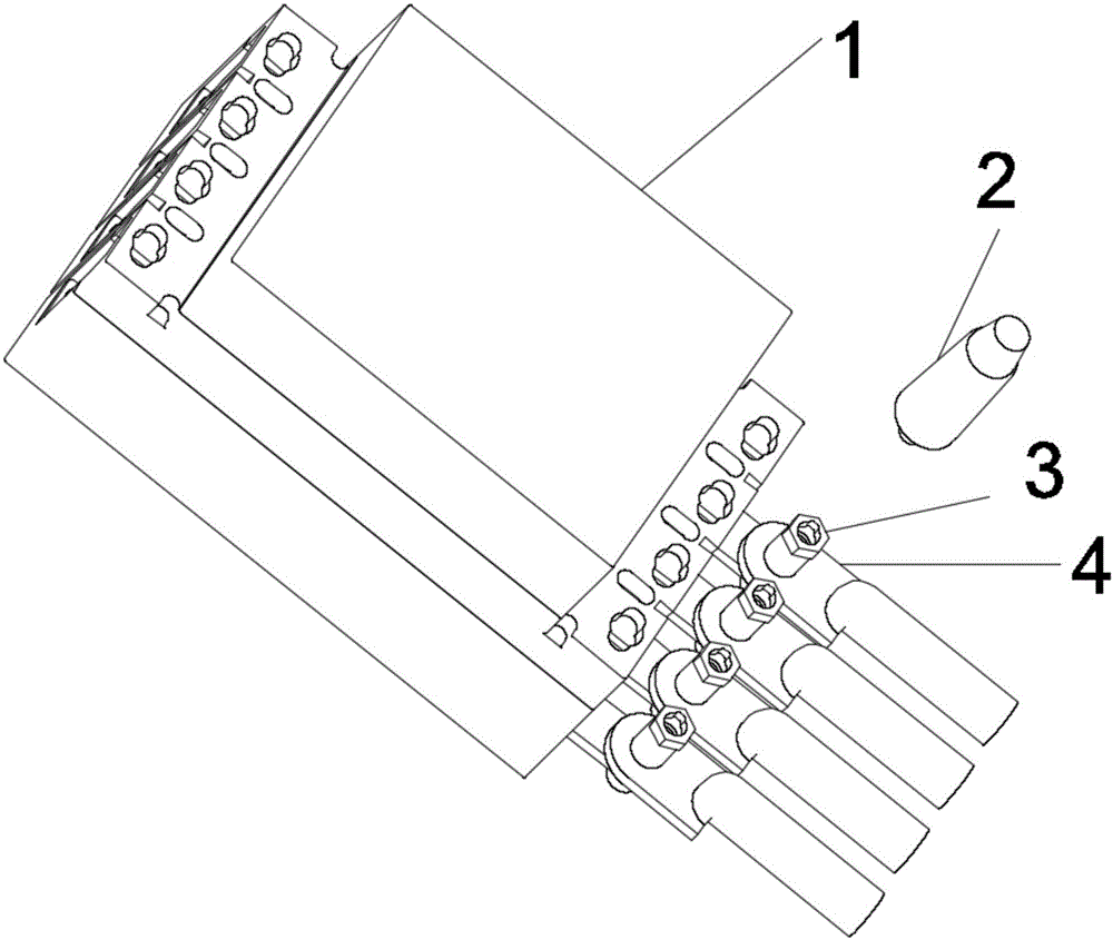
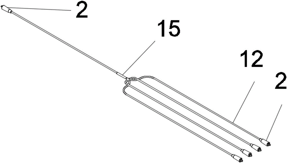
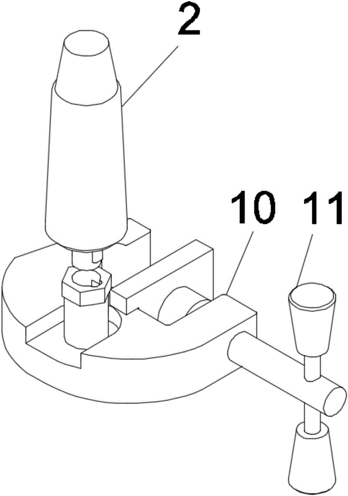
[0021] Such as Figure 1 to Figure 5 As shown, the snap-fit ​​device grounding device of this embodiment includes a switch body 1, a ground wire movable end 2 and a ground wire fixed end 3; 4; the top of the movable terminal 2 of the grounding wire is provided with a terminal connecting rod 5, and the terminal connecting rod 5 is a cylinder, and a protruding key 6 is provided on the side of the terminal connecting rod 5; The top of the wire fixing terminal 3 is provided with a connecting hole 7 ...


PUM


Abstract

The invention discloses a clamp-type equipment grounding device which comprises a switch body, a grounding wire movable terminal and a grounding wire fixation terminal. The grounding wire fixation terminal is arranged at a wiring end of the switch body; the top end of the grounding wire movable terminal is provided with a terminal connection rod; the terminal connection rod is a cylinder body; the side surface of the terminal connection rod is provided with a projection key; the top end of the grounding wire fixation terminal is provided with a connection hole cooperated with the terminal connection rod; the connection hole is provided with a notch; the notch can allow the projection key to pass through cooperatively; the inner wall of the connection hole is provided with a spiral groove; and the spiral groove is cooperated with the projection key, so that the terminal connection rod is allowed to be in locking cooperation with the connection hole. The beneficial effects of the clamp-type equipment grounding device are that the adopted connection device is convenient to use and reliable to connect; and under the condition that the fixation terminal is installed, safe and reliable connection can be achieved only by clamping the movable terminal to the fixation terminal without carrying out fastening operation.

Description

technical field [0001] The invention relates to a grounding device, in particular to a snap-fit ​​equipment grounding device. Background technique [0002] In the past, due to the large size of the clip-type grounding head, it was difficult and unreliable to attach the grounding wire when the switch outlet distance was small or the busbar width was large. Legacy products used clamp-type clamps to connect conductor ends. Due to the large size of the pliers clamp, it is difficult to install the grounding wire on some relatively compact equipment, such as the outgoing line of the distribution line on the user side, due to insufficient space; because it is only fixed by the occlusal force of the clamp, it is easy to install the ground wire due to the small friction force on the surface of the metal conductor. Loosening; the firmness of the connection is related to the size and shape of the conductor at the grounding part, and it is prone to unreliable fixation, which may cause ...

Claims


Application Information

Patent Timeline
Patent Type & Authority Applications(China)
IPC IPC(8): H01R4/66H01R4/28
Inventor 钟家喜黄胜邵孜辉张永强
Owner STATE GRID CORP OF CHINA
Why Eureka
Try Eureka