
Rotary panel structure

A technology of panels and rotating centers, applied in the direction of cabinets/cabinets/drawer parts, etc., can solve the problems of poor independent maintenance, inconvenience, long time for disassembly or maintenance operations, etc., and achieve the effect of large maintenance space

Pending Publication Date: 2015-10-21
GUANGZHOU KINGTELLER TECHNOLOGY CO LTD
View PDF0 Cites 1 Cited by
  • Summary
  • Abstract
  • Description
  • Claims
  • Application Information

AI Technical Summary

Problems solved by technology

[0002] Existing self-service terminals (such as remote video teller machines) are generally detachable and fixed inside the cabinet by screws, etc. The panel used to install the display screen is poor in independent maintenance. When disassembling or maintaining, the staff needs to remove the cabinet After the rear cabinet door is opened and some components in the cabinet are pulled out of the cabinet, the disassembly or maintenance can only be carried out by drilling into the small space inside the cabinet. It is extremely inconvenient for the staff to be limited by the small space during disassembly or maintenance. , and after disassembly or maintenance, it is necessary to push the parts pulled out of the cabinet back to the cabinet and lock the rear cabinet door. It can be seen that the disassembly or maintenance operation takes a long time

Method used


Image

  • Rotary panel structure
  • Rotary panel structure
  • Rotary panel structure

Examples


Embodiment Construction

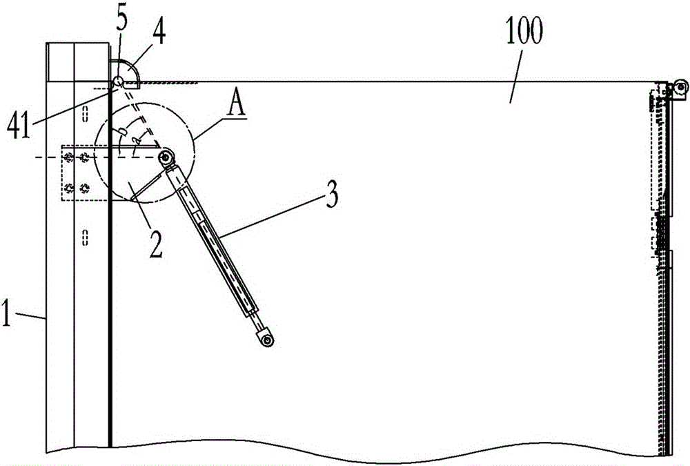
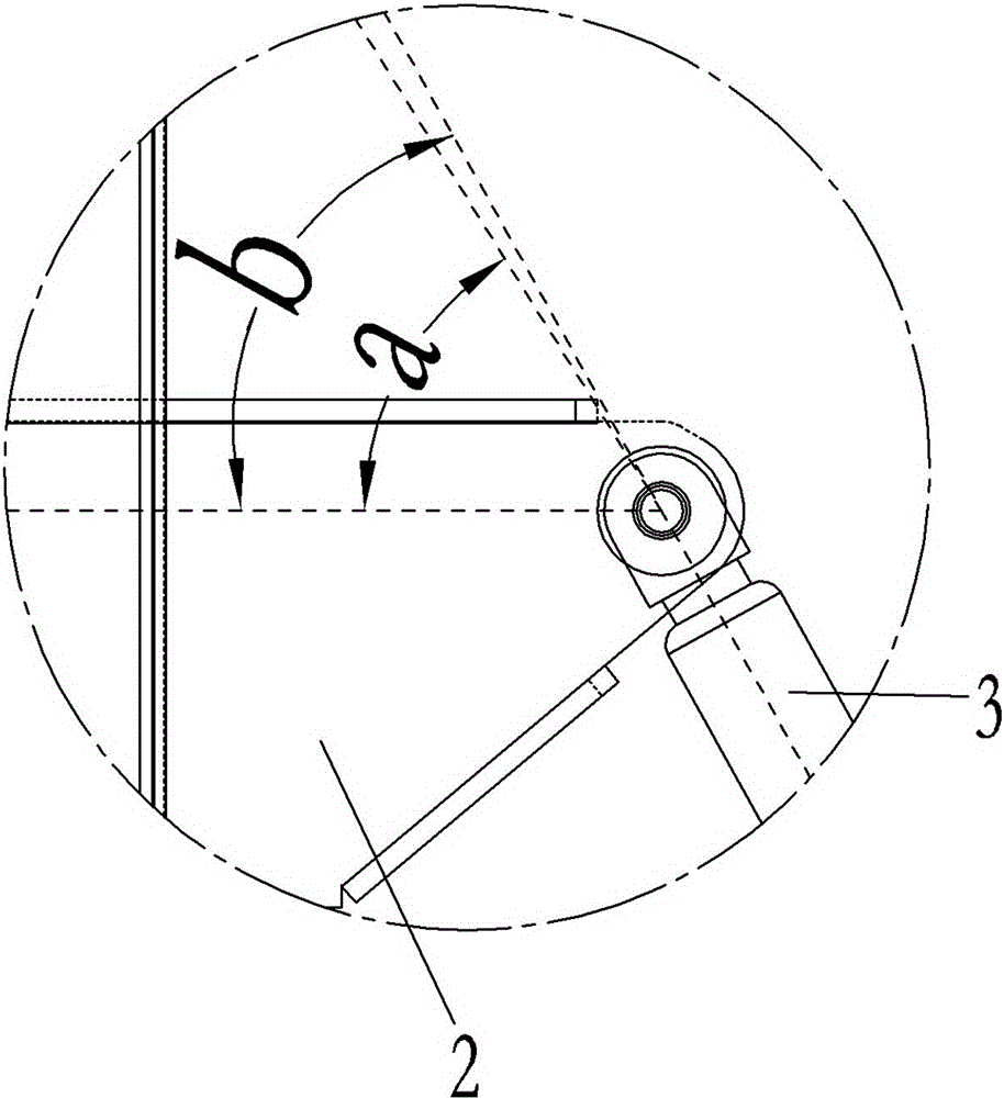
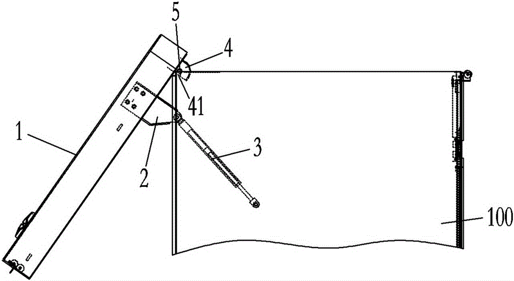
[0012] Such as Figures 1 to 6 As shown, the rotating panel structure includes a panel 1, the top of the panel 1 is rotatably connected to the top front edge of the cabinet 100, and can swing up and down around its rotation center, and the panel 1 is located below its rotation center The hinge seat 2 extending backward is fixed, one end of the gas spring 3 (that is, the end of the pressure rod of the gas spring 3 or the end of the piston rod) is hinged with the hinge seat 2, and the other end (that is, the end of the piston rod of the gas spring 3) end or the end of the pressure rod) is hinged inside the cabinet 100, when the panel 1 is not turned up, the angle b between the thrust direction of the gas spring 3 acting on the hinge seat 2 and the normal line of the panel 1 is slightly larger than the hinge seat The included angle a between the line connecting the center of rotation of 2 and the center of rotation of panel 1 and the normal line of panel 1; The spring 3 can auto...


PUM


Abstract

The invention discloses a rotary panel structure. The top portion of a panel is rotatably connected to the front edge of the top portion of a cabinet body and can swing up and down around a rotation center thereof; the panel is fixedly provided with a hinged support extending backwards at the place under the rotation center thereof; one end of an air spring is hinged with the hinged support, and the other end is hinged inside the cabinet; when the panel is not turned upwards, the included angle between the direction of thrust acting on the hinged support of the air spring and the normal line of the panel is slightly larger than the included angle between the connection line of the rotation center of the hinged support and the rotation center of the panel and the normal line of the panel; and when the panel is turned upwards to a predetermined angle by external force, the air spring can automatically push the panel to turn upwards in place continuously. The whole processes of mounting and dismounting or maintenance can be finished outside the cabinet, so that the maintenance space is large, working staffs do not need to go into the narrow internal space of the cabinet, and independent maintenance of the panel can be realized; and mounting and dismounting or maintenance operation is very convenient, and maintenance time can be reduced greatly.

Description

technical field [0001] The invention relates to a self-service terminal, in particular to a rotating panel structure of the self-service terminal. Background technique [0002] Existing self-service terminals (such as remote video teller machines) are generally detachable and fixed inside the cabinet by screws, etc. The panel used to install the display screen is poor in independent maintenance. When disassembling or maintaining, the staff needs to remove the cabinet After the rear cabinet door is opened and some components in the cabinet are pulled out of the cabinet, the disassembly or maintenance can only be carried out by drilling into the small space inside the cabinet. It is extremely inconvenient for the staff to be limited by the small space during disassembly or maintenance. , and after disassembly or maintenance, it is necessary to push the parts pulled out of the cabinet back to the cabinet and lock the rear cabinet door. It can be seen that the disassembly...

Claims


Application Information

Patent Timeline
Patent Type & Authority Applications(China)
IPC IPC(8): H05K5/03
Inventor 谢清钟刘福黄宜学苏浩
Owner GUANGZHOU KINGTELLER TECHNOLOGY CO LTD
Learn More