
Indoor fan control method and device

A technology of indoor fan and control method, which is applied in heating and ventilation control system, space heating and ventilation control input, control input related to air characteristics, etc., can solve problems such as waste of electric energy, reduce electric energy loss, prevent electric energy wasteful effect

Active Publication Date: 2015-10-28
GD MIDEA HEATING & VENTILATING EQUIP CO LTD +1
View PDF11 Cites 7 Cited by
  • Summary
  • Abstract
  • Description
  • Claims
  • Application Information

AI Technical Summary

Problems solved by technology

As we all know, traditional indoor fans are operated at rated values, especially in order to ensure the heat exchange effect of indoor units, the air volume output of indoor fans has a large margin, resulting in waste of electric energy

Method used


Image

  • Indoor fan control method and device
  • Indoor fan control method and device
  • Indoor fan control method and device

Examples


no. 1 example

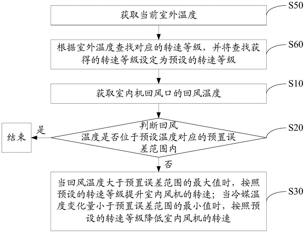
[0062] Further, refer to image 3 , based on the first embodiment of the indoor fan control method of the present invention, in the third embodiment of the indoor fan control method of the present invention, the above indoor fan control method further includes:

[0063] Step S50, obtaining the current outdoor temperature;

[0064] Step S60, searching for the corresponding rotation speed level according to the outdoor temperature, and setting the rotation speed level obtained from the search as the preset rotation speed level.

[0065] It can be understood that the setting of the speed level can be set according to actual needs, for example, when the air conditioner is in the heating operation, a corresponding speed level is set; in the cooling operation, there is a corresponding speed level. In addition, since the outdoor temperature is constantly changing, different speed levels can be set according to different outdoor temperatures to ensure that the above-mentioned return ...

no. 1 example to no. 3 example

[0097] Further, refer to Figure 10 , based on the first to third embodiments of the indoor fan control device of the present invention, in the fifth embodiment of the indoor fan control device of the present invention, the adjustment module 30 includes:

[0098] The second analysis unit 33 is configured to determine the number of speed reduction levels according to the minimum value of the return air temperature and the preset error range;

[0099] The second adjustment unit 34 is configured to control the indoor fan to reduce the speed level according to the current speed level and the number of the reduced speed levels.

[0100] In this embodiment, the greater the difference between the return air temperature and the minimum value of the preset error range, the greater the difference between the current speed level of the indoor fan and the final speed level that needs to be adjusted. For example, when the difference between the return air temperature and the minimum value...


PUM


Abstract

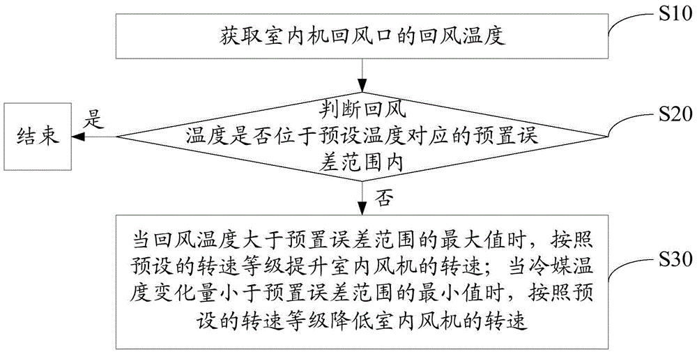
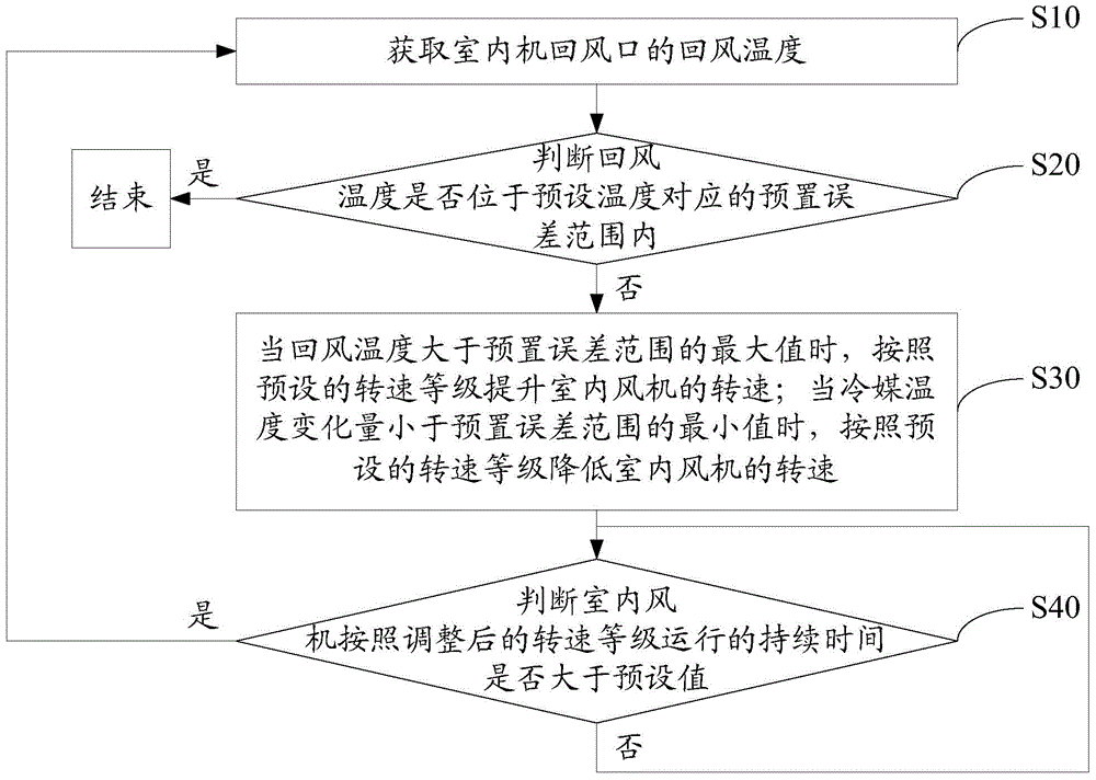
The invention discloses an indoor fan control method. The indoor fan control method comprises the following steps that the air return temperature of an air return inlet of an indoor fan is obtained; whether the air return temperature is within the preset error range corresponding to the preset temperature or not is judged; when the air return temperature is larger than the maximum value of the preset error range, the rotation speed of the indoor fan is increased according to the preset rotation speed grade; when the refrigerant temperature variation is smaller than the minimum value of the preset error range, the rotation speed of the indoor fan is decreased according to the preset rotation speed grade. The invention further discloses an indoor fan control device. Loss of electric energy is reduced, and waste of electric energy is prevented.

Description

technical field [0001] The invention relates to the technical field of air conditioning, in particular to an indoor fan control method and device. Background technique [0002] With the development of air-conditioning technology, the application of air-conditioning has been popularized. In the competition of air conditioners, the energy consumption of air conditioners has become the focus of attention of various manufacturers. As we all know, traditional indoor fans are operated at rated values, especially in order to ensure the heat exchange effect of the indoor unit, the air volume output of the indoor fan has a large margin, resulting in waste of electric energy. [0003] The above content is only used to assist in understanding the technical solution of the present invention, and does not mean that the above content is admitted as prior art. Contents of the invention [0004] The main purpose of the present invention is to provide a method and device for controlling ...

Claims


Application Information

Patent Timeline
Patent Type & Authority Applications(China)
IPC IPC(8): F24F11/00
CPCF24F11/30F24F11/62F24F11/64F24F11/77F24F2110/10Y02B30/70
Inventor 万永强许永锋熊美兵李波杨元涛舒文涛钱小龙
Owner GD MIDEA HEATING & VENTILATING EQUIP CO LTD
Learn More