
Steam compression type air conditioning system

An air-conditioning system and a compression-type technology, which are applied in the field of vapor-compression air-conditioning systems, can solve the problems of large refrigerant and heating differences in charging capacity, difficult working conditions of cooling and heating air conditioners, etc., and achieve the effect of improving the energy efficiency ratio.

Active Publication Date: 2015-10-28
GUANGZHOU INST OF ENERGY CONVERSION - CHINESE ACAD OF SCI
View PDF9 Cites 1 Cited by
  • Summary
  • Abstract
  • Description
  • Claims
  • Application Information

AI Technical Summary

Problems solved by technology

The difference in working conditions in winter and summer leads to large differences in the charging volume of working fluid in cooling and heating. Therefore, in the actual process, the filling volume of working fluid is often a compromise value, making it difficult for the heating and cooling air conditioner to work at its best. state

Method used


Image

  • Steam compression type air conditioning system
  • Steam compression type air conditioning system

Examples


Embodiment 1

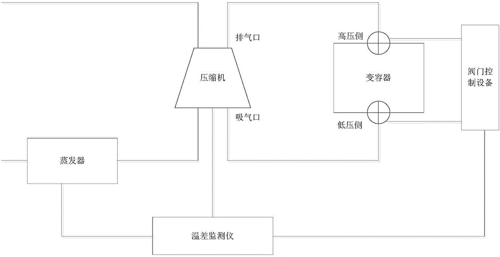
[0019] The vapor compression air-conditioning system of the present invention includes a connected compressor and an evaporator, as well as a variable container, a temperature difference monitor and a valve control device.

[0020] Such as figure 1 As shown, the high-pressure side of the variable vessel communicates with the discharge port of the compressor for receiving excess working fluid in the compressor, and the low-pressure side communicates with the suction port of the compressor for returning the working fluid to the compressor. In addition, the variable vessel also uses valves to control the on-off of the high-pressure side and the low-pressure side, that is, valves are respectively set on the high-pressure side and the low-pressure side. quality container. The temperature sensor of the temperature difference monitor, one is set at the air inlet of the compressor, and the other is set in the evaporator, the output terminal of the temperature difference monitor is co...

Embodiment 2

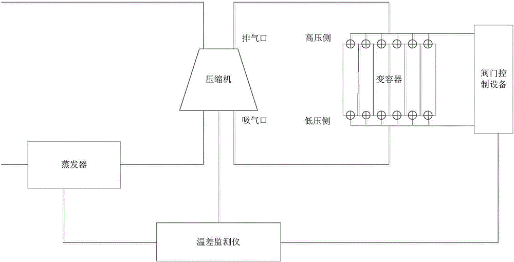
[0025] The vapor compression air-conditioning system of this embodiment is based on the first embodiment, and the variable capacitor is improved. Specifically, multiple partitions are used to divide the variable container into multiple spaces, such as figure 2 As shown, each space is provided with a valve on the high-pressure side and low-pressure side, and a part of the space is used as a space for storing working fluid. In this part of the space, the valve on the high-pressure side is opened, and the valve on the low-pressure side is closed; the other part of the space is used as a space for releasing the working fluid. In this part of the space, the valve on the low-pressure side is opened, and the valve on the high-pressure side is closed.

[0026] In this embodiment, the integrated space of the variable vessel is divided into multiple independent spaces, and a group of high and low pressure side valves are set for each space to control them separately, in order to preven...


PUM


Abstract

The invention discloses a steam compression type air conditioning system which comprises a compressor, an evaporator, a varactor, a temperature difference monitor and a valve control system. The high-pressure side of the varactor is communicated with an exhaust port of the compressor, and the low-pressure side of the varactor is communicated with an air suction port of the compressor. According to the temperature difference of the air suction port of the compressor and the evaporator, working medium conditions are judged. A high-pressure side valve and a low-pressure side valve are controlled to be opened and closed according to the working medium conditions. The high-pressure side valve is opened and the low-pressure side valve is closed when working media are excessive, and the working media are loaded into the varactor from the compressor. The low-pressure side valve is opened and the high-pressure side valve is closed when working media are insufficient, and the working media are released from the varactor to the compressor. Thus, the filling quantity of the working media in a working medium circulating loop is adjusted, the energy efficiency ratio of the system is increased, and the aim that system performance adapts to the working conditions is achieved.

Description

technical field [0001] The invention relates to the technical field of refrigeration and heating, in particular to a vapor compression air-conditioning system. Background technique [0002] The working process of the vapor compression air conditioning system is to absorb heat from a low-temperature heat source through the working medium, and release heat to a high-temperature heat source through a compressor to raise the temperature. Based on the consideration of economy and efficiency, there is an optimal heat transfer temperature difference between the condensation temperature of the working fluid and the high-temperature heat source. Similarly, there is an optimal heat transfer temperature difference between the evaporation temperature of the working fluid and the low-temperature heat source. However, this optimal heat transfer temperature difference often only exists under design conditions. In the actual application process, the temperature difference of the optimal he...

Claims


Application Information

Patent Timeline
Patent Type & Authority Applications(China)
IPC IPC(8): F25B1/00F25B49/02
CPCF25B49/02F25B41/20
Inventor 黄宏宇邓立生窪田光宏何兆红小林敬幸呼和涛力陈勇
Owner GUANGZHOU INST OF ENERGY CONVERSION - CHINESE ACAD OF SCI
Learn More