Method and device for generating mechanical reciprocating bistable motion by virtue of electromagnetism

A bistable, mechanical technology, applied in electromechanical devices, electrical components, etc., can solve problems affecting system performance and reliability, achieve reliable bistable characteristics, simplify device structure, and reduce manufacturing and maintenance costs.

Inactive Publication Date: 2011-10-12
戴珊珊
View PDF5 Cites 27 Cited by
  • Summary
  • Abstract
  • Description
  • Claims
  • Application Information

AI Technical Summary

Problems solved by technology

The traditional mechanical reciprocating motion is powered by the motor or the output shaft of the engine directly, and the rotational torque of the motor or the power output shaft of the engine is transformed into a mechanical transformation mechanism through a specific mechanical conversion mechanism, such as a crankshaft connecting rod mechanism, an eccentric wheel mechanism, a sector gear mechanism, etc. Reciprocating motion, due to the need to go through a mechanical conversion mechanism, will inevitably affect the performance and reliability of the entire system

Method used


Image

  • Method and device for generating mechanical reciprocating bistable motion by virtue of electromagnetism
  • Method and device for generating mechanical reciprocating bistable motion by virtue of electromagnetism
  • Method and device for generating mechanical reciprocating bistable motion by virtue of electromagnetism

Examples


Embodiment 1

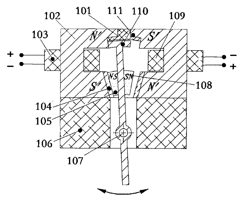
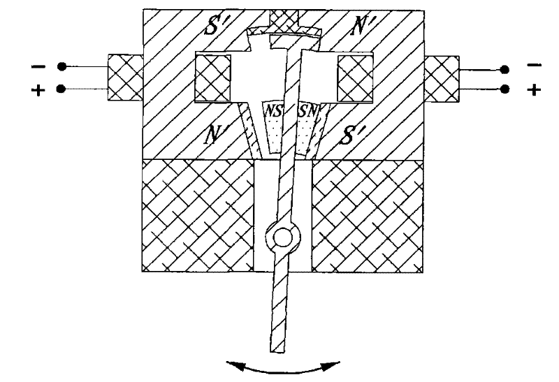
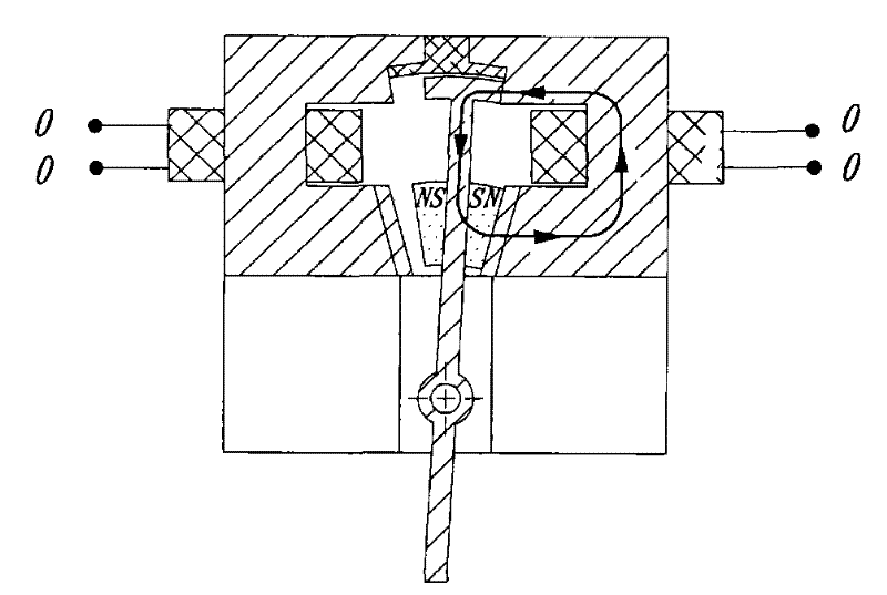
[0032] This embodiment is an example in which an alternating current is passed into an excitation coil to excite the soft magnet to generate an alternating magnetic field, thereby realizing mechanical reciprocating swing. The device structure of this embodiment is as attached figure 1 , 2 , 3 shown. Two "C"-shaped soft magnets 102, 111 have opposite openings, and excitation coils 103, 109 wrap the soft magnets 102, 111. The magnetic field leads above the two "C"-shaped soft magnets are separated by the magnetic circuit 101, and the two "C" There is a large magnetic field air gap at the magnetic field lead-out end under the "shaped soft magnet, and the permanent magnets 105 and 108 are symmetrically attached to the active arm of the magnetic pendulum 110, and the S poles of the two permanent magnets are relatively attached to the magnetic pendulum 110. On the left and right sides, the permanent magnets 105 and 108 attached to the magnetic pendulum bar 110 are placed between t...

Embodiment 2

[0036] This embodiment is an example of generating an alternating magnetic field on the soft magnet by rotating the permanent magnet, thereby generating mechanical reciprocating swing. The device structure of this embodiment is as attached Figure 4 , 5 , 6 shown.

[0037]In this example, the four pieces of soft magnets are divided into left and right sides, the upper left soft magnet 203 and the lower left soft magnet 206 are separated by the magnetic circuit 204, the upper right soft magnet 216 and the lower right soft magnet 211 The magnetic circuit is cut off by the spacer magnet 214, the soft magnet 203 and the soft magnet 206 surround the left rotating permanent magnet 205, and there is a very small air gap between the left rotating permanent magnet, and the soft magnetic body 216 and the soft magnet 211 surround the right rotating permanent magnet. Magnet 215, and there is a very small air gap between the right side rotating permanent magnet, the magnetic circuit is a...

Embodiment 3

[0040] This embodiment is an example in which an alternating current passes through an excitation coil to excite the soft magnet to generate an alternating magnetic field, thereby realizing mechanical reciprocating linear motion. The device in this example is attached Figure 7 , 8 , as shown in 9.

[0041] In this example, a push rod 301 of non-magnetic material is fixed vertically at the center of a magnetically conductive substrate 306, and two permanent magnets 304 of the same size and opposite polarity are pasted on the upper and lower surfaces of the magnetically conductive substrate 306 And the permanent magnet 310, that is, the two permanent magnet N poles are relatively attached to the upper and lower sides of the magnetically conductive substrate 306, and the magnetic pole directions of the two permanent magnets are consistent with the axial direction of the push rod 301, and the push rod is fixedly attached to the position of the permanent magnet It is placed betw...


PUM


Abstract

The invention relates to a method and device for generating mechanical reciprocating bistable-state motion by virtue of electromagnetism. The method is characterized by comprising the following steps: jointing two identical permanent magnets symmetrically on a motion component; placing the parts, adhered to the permanent magnets, of the motion component between two magnetic pole air gaps of an alternating magnetic field; sucking, shutting and repelling the permanent magnets on the motion component repeatedly by virtue of two magnetic poles by the alternating magnetic field so as to drive the motion component to perform reciprocating motion; and regulating the position and structure between the motion component and the two magnetic poles of the alternating magnetic field, thus the motion component can be enabled to perform reciprocating swing and reciprocating linear motion. The invention also provides the device for generating mechanical reciprocating bistable motion by virtue of electromagnetism; through exciting or rotating the permanent magnets by an alternating power source, the alternating magnetic filed is formed on a soft magnet; and the parts, to which the permanent magnets are attached, of a swinging rod and a pushing rod are placed in the magnetic air gaps of the soft magnet. According to the invention, the characteristics of the permanent magnets that the permanent magnets are stressed in the alternating magnetic field and the permanent magnetic tends to be stable once being sucked with the magnetic poles of the alternating magnetic field are utilized, the structure of the device is simplified, and the state is maintained to be stable without energy consumption.

Description

technical field [0001] The invention relates to the technical field of electromechanical integration devices or devices, in particular to a method and a device for directly obtaining mechanical reciprocating bistable motion by electromagnetic force. Background technique [0002] Reciprocating motion is a common form of motion in mechanical motion and has a wide range of uses. The traditional mechanical reciprocating motion is powered by the motor or the output shaft of the engine directly, and the rotational torque of the motor or the power output shaft of the engine is transformed into a mechanical transformation mechanism through a specific mechanical conversion mechanism, such as a crankshaft connecting rod mechanism, an eccentric wheel mechanism, a sector gear mechanism, etc. The reciprocating motion will inevitably affect the performance and reliability of the entire system due to the need to pass through a mechanical conversion mechanism. Contents of the invention ...

Claims


Application Information

Patent Timeline
Patent Type & Authority Applications(China)
IPC IPC(8): H02K33/18
Inventor 戴珊珊朱石柱
Owner 戴珊珊
Why Eureka
Try Eureka