Gas flow measuring device for large-diameter pipes

A technology of gas flow and measuring device, which is applied in the field of pipeline internal flow and bluff body flow, and fluid mechanics, and can solve the problems of high performance requirements of differential pressure sensors, unsuitable for long-term online measurement, and inability to measure gas drainage pipelines. , to achieve the effect of easy production scale, simple structure and low cost

Inactive Publication Date: 2015-10-28
INST OF MECHANICS - CHINESE ACAD OF SCI +1
View PDF5 Cites 9 Cited by
  • Summary
  • Abstract
  • Description
  • Claims
  • Application Information

AI Technical Summary

Problems solved by technology

The vortex flowmeter is only suitable for the measurement of high-velocity media, and it will not be able to measure the low-flow gas drainage pipeline
To measure the flow rate of low-velocity media, it is necessary to reduce the gas pipeline and increase the gas flow rate through the vortex flowmeter, but this will bring additional permanent pressure loss and variable diameter investment and installation problems
In addition, the vortex flowmeter is also very sensitive to the vibration of the surrounding environment, and also has very strict requirements for the installation of straight pipe sections
To accurately measure the flow velocity of the pipeline medium, the standard pitot tube flowmeter must select a micro differential pressure that can stably measure 0.1Pa, which requires a high performance of the differential pressure sensor, and the pressure hole at the front of the flowmeter is extremely small, so it is easy to It is blocked, therefore, it is not suitable for long-term online measurement, and it is suitable for the measurement of coal mine on-site flow

Method used


Image

  • Gas flow measuring device for large-diameter pipes
  • Gas flow measuring device for large-diameter pipes
  • Gas flow measuring device for large-diameter pipes

Examples


Embodiment Construction

[0042] The following examples are only used to illustrate the present invention, but are not used to limit the scope of the present invention. Unless otherwise specified, the methods used are commonly used methods in the art.

[0043] The device for measuring gas flow in large-diameter pipelines disclosed in the present invention will be described below with reference to the accompanying drawings and embodiments.

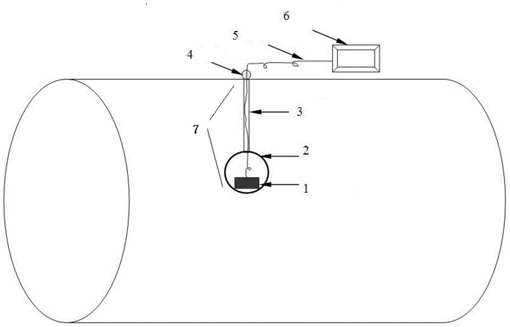
[0044] figure 1 It is a specific embodiment of the gas flow measuring device described in the present invention, which includes a swinging part 7 arranged in the gas pipeline fluid and a device for measuring the swinging angle of the swinging part.

[0045] The swing part 7 of the present invention may include a fixed end 4 and a swing ball 2, the swing ball 2 can freely swing relative to the fixed end 4 under the action of an external force, the swing ball 2 is exposed to the fluid passing through the pipeline, The fixed end 4 is arranged outside the pipe; the fi...


PUM


Abstract

The invention relates to a gas flow measuring device suitable for large-diameter gas pipelines and smoke pipelines. The gas flow measuring device of the invention mainly comprises a swing component arranged in gas pipeline fluid and a device for measuring the swing angle of the swing component. Compared with the prior art, the measuring device of gas flow is a plug-in measuring device which has the advantages of simple structure and convenient measurement. The gas flow measuring device is suitable for measurement of large flow, suitable for large-diameter pipes, and is especially suitable for determination of gas flow in large-diameter gas pipelines and smoke pipelines; the gas flow measuring device is slightly affected by fouling degree of a measured medium, such as solid or liquid impurities; and the gas flow measuring device can be applicable to pipelines of a certain oblique angle. The gas flow measuring device has the advantages of high measurement range ratio, low permanent pressure loss, little possibility of being blocked and worn, convenient installation, simple structure, low cost, simple operation and easiness in large-scale production. According to the gas flow measuring device, requirements for straight pipe sections are lower, and the gas flow measuring device can be used as long as the gas flow measuring device is not too close to a bent pipe section.

Description

technical field [0001] The invention relates to the field of fluid mechanics, especially the field of pipeline internal flow and blunt body flow around. Specifically, the invention relates to a gas flow measurement device for a blunt body exposed to fluid in a large-diameter pipeline. By means of the swing of the structure Kinematics measure gas volume flow in pipes. Background technique [0002] In the coal mining industry, in order to strengthen the importance of controlling gas disasters through gas drainage, the State Administration of Coal Mine Safety and Supervision formulated the policy of "gas drainage first, then mining, wind production, monitoring and monitoring" in 2002, clearly It is proposed that the quality of gas drainage should be firstly paid attention to in gas control, and the monitoring and monitoring can be realized by measuring the gas flow, so as to reduce the occurrence of gas disasters. Because the gas has a series of characteristics such as high hu...

Claims


Application Information

Patent Timeline
Patent Type & Authority Applications(China)
IPC IPC(8): G01F1/05G01P11/00
Inventor 钟兴福张英利林黎明延鹏斌吴应湘
Owner INST OF MECHANICS - CHINESE ACAD OF SCI
Why Eureka
Try Eureka