Method for measuring gas flow of large-diameter pipe

A measurement method and technology for gas flow, which are applied in the fields of fluid mechanics, pipeline internal flow and bluff body flow, which can solve the problems of inconvenient transportation and installation, small pipeline diameter, large permanent pressure loss, etc. Blockage wear, small permanent pressure loss effect

Inactive Publication Date: 2015-11-11
INST OF MECHANICS - CHINESE ACAD OF SCI
View PDF5 Cites 3 Cited by
  • Summary
  • Abstract
  • Description
  • Claims
  • Application Information

AI Technical Summary

Problems solved by technology

[0004] For example, the orifice flowmeter has a simple structure, low cost, and no rotating parts. The pressure-taking hole is not easy to be blocked by dirty media, and is suitable for small-diameter pipelines. The permanent pressure loss is large; the pressure loss of the vortex flowmeter is small, but the measured gas flow rate is low or the pipe diameter is small (generally, the measured fluid Re number is not more than 10 5 ), is more sensitive to environmental vibration, and the long-term operation stability of the site is poor, and the measurement results are related to the insertion depth of the flowmeter, and have higher requirements for the straight pipe section; Point flow rate and flow rate, however, due to the thinner insertion rod and smaller pressure hole, it is easy to block, so it is not suitable for long-term online measurement of gas flow rate; the precession vortex flowmeter has no rotating parts, corrosion resistance, stable and reliable, but is suitable for small Larger diameter pipes have large permanent pressure loss, poor site adaptability, and are easily affected by the measured medium, especially dirty gas. The guide vanes are easy to scale and need to be cleaned frequently; The meter has the characteristics of self-rectification with less requirements for straight pipe sections, self-cleaning that is not easily stained by the measured medium, small pressure loss (so it is suitable for low negative pressure drainage pipelines), high stability and good field adaptability, etc. But its overall structure is more complicated, and it is more inconvenient to transport and install.

Method used


Image

  • Method for measuring gas flow of large-diameter pipe
  • Method for measuring gas flow of large-diameter pipe
  • Method for measuring gas flow of large-diameter pipe

Examples


Embodiment Construction

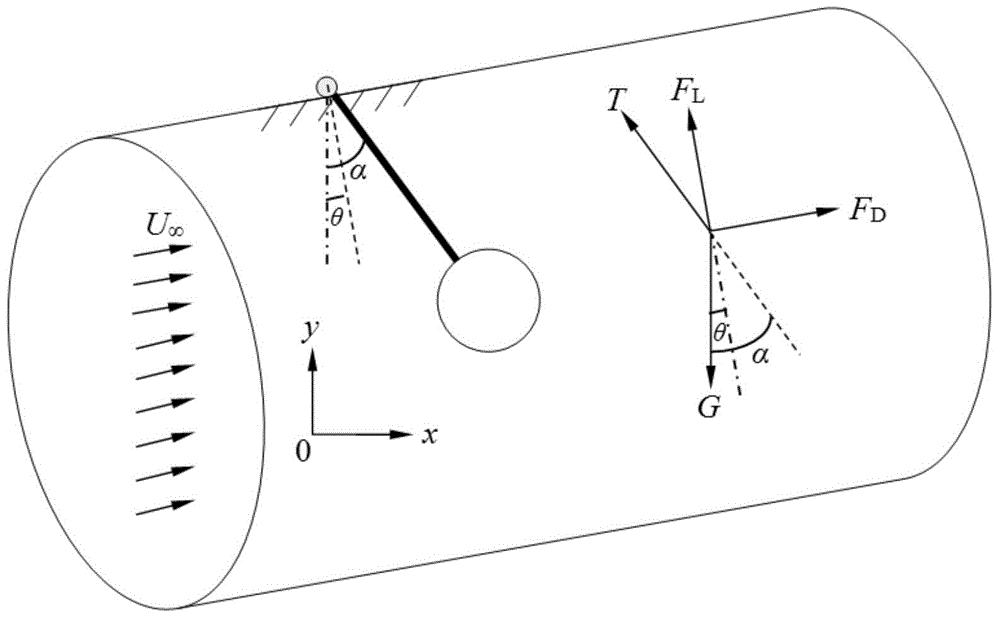
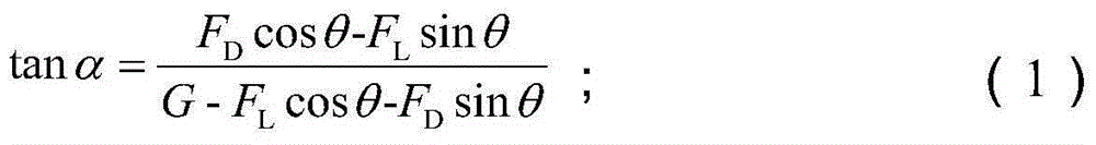
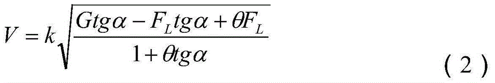
[0038] The method for measuring gas flow in large-diameter pipelines disclosed in the present invention is a method for measuring when the swing structure deflects under the action of fluid load to achieve force balance. The schematic diagram of its layout and principle analysis is as follows figure 1 As shown, the supporting structure in the flow measuring device is suspended on the top of the pipeline; under the action of the average incoming flow in the pipeline, the swinging structure in the measuring device deviates from the initial position, and reaches a force balance at a certain deflection angle; the measuring device The signal sensor and the microelectronic circuit control device in the pipeline are converted to obtain and output the average flow velocity or flow rate of the pipeline under the corresponding deflection.

[0039] The above-mentioned device is used to measure the air under normal temperature and pressure in a wind tunnel with a diameter of 300 mm (the ax...


PUM


Abstract

The invention relates to a gas flow measuring method. The principle of the method is that fluid loading is generated on a measuring device by gas under specific velocity distribution in a pipeline, the measuring device deviates from the initial position and swings under the action, and then the average deflection angle of the device deviating from the initial position is measured, so that the relations between the average deflection angle and gas flow rate and corresponding volume flow rate are obtained. Compared with the prior art, the method has the advantages that measuring range ratio is large, the method is suitable for pipelines with large diameters, blocking and abrasion can not be caused easily, permanent pressure loss is small, installation is convenient, the influence of the stained degree of a measured medium is small, only a short straight pipe section is required, and the method is adaptable to a pipeline with a certain inclination angle, suitable for pipes with large diameters, and especially suitable for measurement of the gas flow of large-diameter gas pipelines and smoke pipelines.

Description

technical field [0001] The present invention relates to the field of fluid mechanics, especially the field of pipeline internal flow and blunt body flow around. Volume flow method. Background technique [0002] In industries such as petroleum, metallurgy, chemical industry, and coal mining, there are many large-diameter pipelines that require real-time measurement of gas flow. Many of the gases contain a lot of dust, which is easy to deposit, and the gas density will change with temperature and pressure changes. , these factors will affect the flow measurement accuracy. In addition, the installation of flowmeters on large-diameter pipelines, the limitation of production site space and front and rear straight pipe sections, and the level of installation and maintenance inspection, these factors will also affect the reliability, stability and practical accuracy of flowmeters. In particular, the safety requirements of coal mine gas drainage and the particularity of gas have p...

Claims


Application Information

Patent Timeline
Patent Type & Authority Applications(China)
IPC IPC(8): G01F1/05G01P11/00
Inventor 钟兴福林黎明吴应湘张军马乃庆
Owner INST OF MECHANICS - CHINESE ACAD OF SCI
Why Eureka
Try Eureka