
Method for detecting work state of converter

A working state and converter technology, applied in the direction of measuring electrical variables, instruments, measuring electricity, etc., can solve the problems of IGBT drive signal loss, fatigue work, converter IGBT damage, etc.

Active Publication Date: 2015-10-28
CSR ZHUZHOU ELECTRIC LOCOMOTIVE RES INST
View PDF6 Cites 6 Cited by
  • Summary
  • Abstract
  • Description
  • Claims
  • Application Information

AI Technical Summary

Problems solved by technology

However, if the IGBT failure, damage or loss of the IGBT driving signal is not detected in time, it will cause the IGBT of other phases or the upper bridge arm and the lower bridge arm to work for a long time due to fatigue, and even lead to the damage of the entire converter IGBT
[0004] However, in the prior art, there is no device that can effectively detect the IGBT failure, damage, or loss of IGBT drive signal of a certain bridge arm, the lower tube, or the entire bridge arm of the converter.

Method used


Image

  • Method for detecting work state of converter
  • Method for detecting work state of converter
  • Method for detecting work state of converter

Examples


Embodiment Construction

[0044] The implementation of the present invention will be described in detail below in conjunction with the accompanying drawings and examples, so as to fully understand and implement the process of how to apply technical means to solve technical problems and achieve technical effects in the present invention. It should be noted that, as long as there is no conflict, each embodiment and each feature in each embodiment of the present invention can be combined with each other, and the formed technical solutions are all within the protection scope of the present invention.

[0045] Also, in the following description, for purposes of explanation, numerous specific details are set forth in order to provide a thorough understanding of embodiments of the invention. It will be apparent, however, to one skilled in the art that the present invention may be practiced without the specific details or in the particular manner described.

[0046] Aiming at the problem that the existing meth...


PUM


Abstract

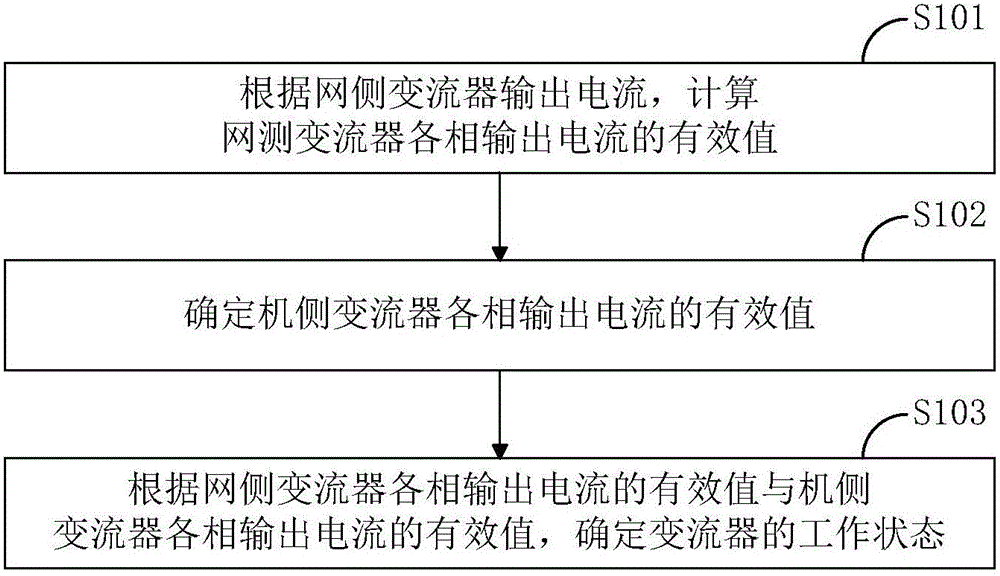
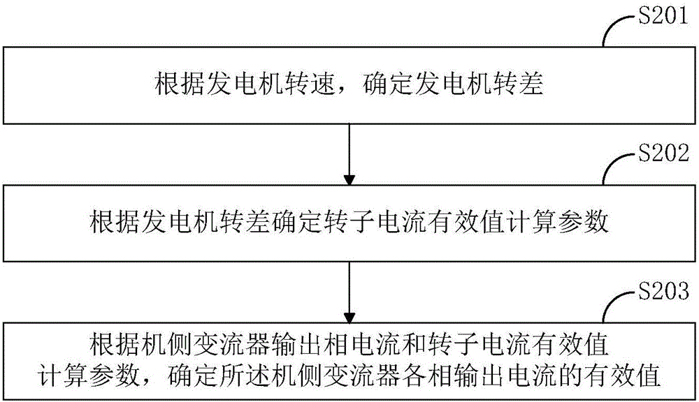
The invention discloses a method for detecting the work state of a converter. The method includes: an effective value determination step of an output current of a generator side converter- determining the effective value of each phase of the output current of the generator side converter according to the rotating speed of a motor; and a work state determination step of the converter- determining the work state of the converter according to the effective value of each phase of the output current of the generator side converter. According to the method, IGBT failure and damage to an upper IGBT and a lower IGBT of a leg or the whole leg of the converter or the state of IGBT driving signal loss can be effectively detected in time, the converter can stop working in time, the further damage to the converter and related devices and circuits is prevented.

Description

technical field [0001] The invention relates to the technical field of power electronics, in particular to a method for detecting the working state of a converter. Background technique [0002] As an environmentally friendly power generation method that does not pollute and utilizes renewable resources, wind power has become one of the most promising renewable energy technologies. Wind power generation has become a focus and focus of competing development in countries all over the world, and the market prospect is broad. However, with the increase in the number and capacity of wind power generating units, the quality of wind turbines has become increasingly prominent. The quality and reliability of the converter as the brain of the wind turbine is more valued by the majority of wind power owners and related technical R&D personnel. [0003] At present, after the IGBT of the upper tube, the lower tube, or the entire bridge arm of a certain bridge arm of the converter fails,...

Claims


Application Information

Patent Timeline
IPC IPC(8): G01R31/00
Inventor 徐凤星佘岳张少云盛建科邬冬临谭宇王继丽黄禹文
Owner CSR ZHUZHOU ELECTRIC LOCOMOTIVE RES INST
Learn More