Conversion method of architectural structure model

A technology of architectural structures and models, applied in special data processing applications, instruments, electrical digital data processing, etc., can solve difficult, unfeasible, and immature problems, reduce transformation combinations, realize reverse transformation, and reduce docking difficulty Effect

Active Publication Date: 2015-10-28
TONGJI UNIV ARCHITECTURAL DESIGN INST GRP CO LTD
View PDF2 Cites 13 Cited by
  • Summary
  • Abstract
  • Description
  • Claims
  • Application Information

AI Technical Summary

Problems solved by technology

[0003] However, similar to the evolution of cars from straight lines to more aerodynamic and graceful streamlines, with the development of computer-aided design technology, the shapes of many contemporary buildings have become more complex and diverse due to the needs of form or function
These structures with complex spatial shapes cannot be described by the traditional architectural axis method, so the traditional method of directly establishing a wireframe model in finite element software for analysis based on architectural drawings and axes is becoming more and more difficult, and in many cases it is even completely unfeasible
[0004] Since the format of finite element analysis software is not uniform, it is difficult to convert in various finite element software. Although there are some conversion tools on the market, such as figure 2 As shown, but due to the large number of finite element software and different versions, many converters are needed, and the conversion results are uneven.
Building Information Modeling (BIM) technology is a possible solution in the future, but because the corresponding computer software and hardware technology is far from mature, and a large number of engineering designers are still very unfamiliar with BIM technology

Method used


Image

  • Conversion method of architectural structure model
  • Conversion method of architectural structure model
  • Conversion method of architectural structure model

Examples


Embodiment Construction

[0037] The present invention will be described in detail below in conjunction with the accompanying drawings and specific embodiments. This embodiment is carried out on the premise of the technical solution of the present invention, and detailed implementation and specific operation process are given, but the protection scope of the present invention is not limited to the following embodiments.

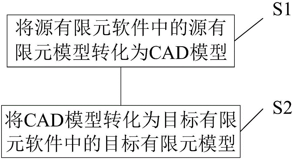
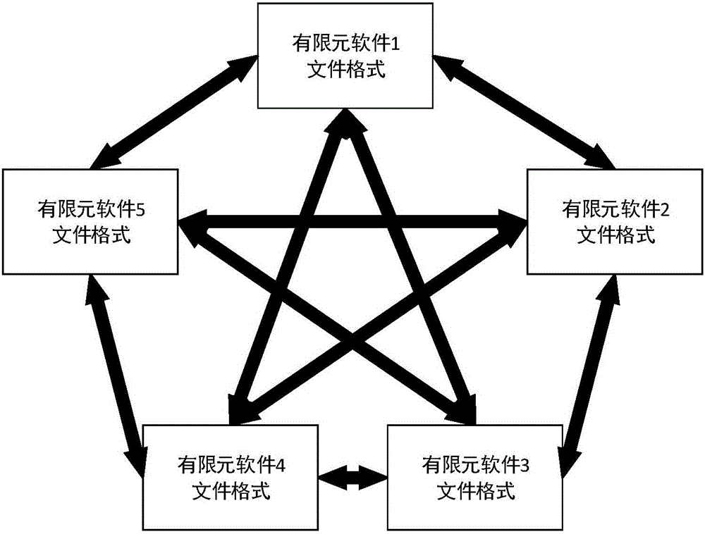
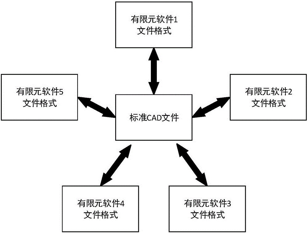
[0038] A building structure model conversion method, used for the mutual conversion of building structure models between different finite element software, such as figure 1 shown, including steps:

[0039] S1: Convert the source finite element model in the source finite element software into a CAD model, and the CAD model is a three-dimensional model, including the following steps:

[0040] S11: Merge the units with the same properties in the source finite element model into one component to obtain multiple components;

[0041] S12: Create a layer for each component in the CAD file...


PUM


Abstract

The invention relates to a conversion method of an architectural structure model, and is used for carrying out mutual conversion among different pieces of finite element software for the architectural structure model. The conversion method comprises the following steps: S1: converting a finite element model in the finite element software into a CAD (Computer-Aided Design) model; and S2: converting the CAD model into a target finite element model in target finite element software. Compared with the prior art, the conversion method causes a CAD file to become a transfer station used for the conversion of various pieces of finite element software. Since traditional finite element analysis software has multifarious data formats and a CAD file format has a relatively uniform standard, a pairwise-conversion combination has a huge amount among finite element software, a software interface is difficult in development, the CAD file stores unit key information, required conversion combinations can be greatly reduced through CAD conversion, and a development difficulty is lowered.

Description

technical field [0001] The invention relates to the technical field of building structures, in particular to a method for transforming building structure models. Background technique [0002] The finite element method is the most important technique in the field of structural analysis today. After decades of development, the finite element method has been quite mature, and many reliable engineering-oriented commercial software have appeared, including general finite element software (such as ANSYS, ABAQUS), and special finite element software in the field of civil engineering (such as SAP2000, Midas). etc. The finite element model stores the attributes of the component elements except the geometric information. At present, there is no uniform file format standard, and the file formats of various finite element analysis software on the market are different. Simple modeling methods are usually integrated in finite element software, which can meet the modeling requirements of ...

Claims


Application Information

Patent Timeline
Patent Type & Authority Applications(China)
IPC IPC(8): G06F17/50
Inventor 黄卓驹丁洁民张峥张月强
Owner TONGJI UNIV ARCHITECTURAL DESIGN INST GRP CO LTD
Why Eureka
Try Eureka