Double-station winding machine for high-tension coil of three-dimensional wound core dry type transformer

A technology of dry-type transformers and high-voltage coils, which is applied in coil manufacturing and other directions, and can solve the problems of low winding efficiency, long auxiliary time, and tediousness of single-phase winding machines

Active Publication Date: 2015-10-28
JIANGXI HANS POWER TECH
View PDF5 Cites 9 Cited by
  • Summary
  • Abstract
  • Description
  • Claims
  • Application Information

AI Technical Summary

Problems solved by technology

[0003] If a conventional single-phase winding machine is used to wind such a coil with a segmented layer structure, it is more cumbersome, because the single-phase winding machine has only one winding station, and the high-voltage coil can only be wound one by one. After winding the coil section with the same starting line end position, turn around and install the transformer body, and then wind the adjacent coil section with the opposite starting line end position in the winding high-voltage coil phase by phase; after winding the three-phase high-voltage coil, the transformer The body needs to be turned around once, installed twice, and flipped four times, so the winding efficiency of the single-phase winding machine is relatively low, and the auxiliary time is relatively long.

Method used


Image

  • Double-station winding machine for high-tension coil of three-dimensional wound core dry type transformer
  • Double-station winding machine for high-tension coil of three-dimensional wound core dry type transformer
  • Double-station winding machine for high-tension coil of three-dimensional wound core dry type transformer

Examples


Embodiment Construction

[0119] The present invention will be described in further detail below in conjunction with the accompanying drawings.

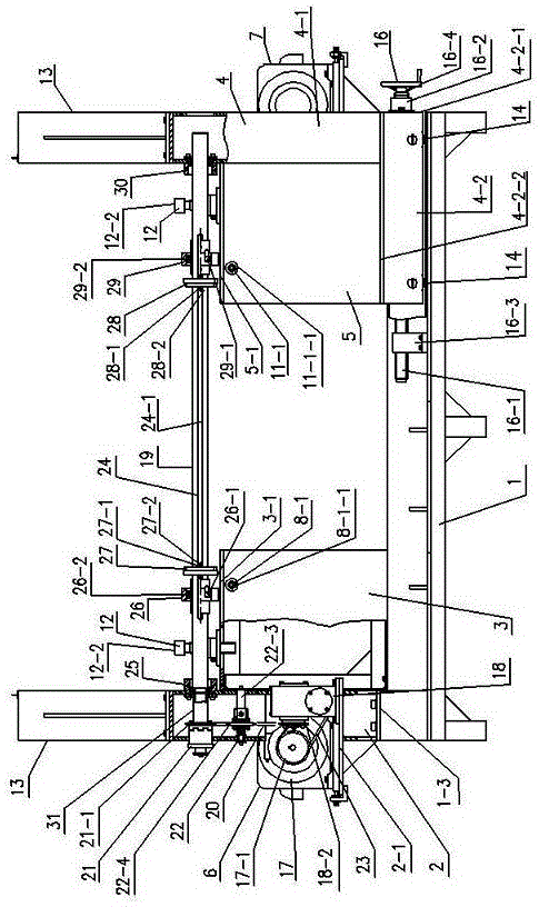
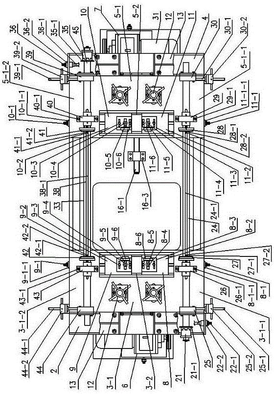
[0120] Such as Figure 1 to Figure 4 As shown, a three-dimensional three-dimensional wound core dry-type transformer high-voltage coil double-position winding machine includes a base 1, a left wall board 2, a left stand 3, a right wall board 4, a right stand 5, and a left wall board 2. The winding power device 6, the left supporting wheel dragging mechanism 8 on the left platform 3 tables, the right supporting wheel supporting mechanism 9 on the left platform 3 tables, the winding power device 7 on the right wallboard 4, the right The left supporting wheel dragging mechanism 10 on the platform of platform 5, the right supporting wheel supporting mechanism 11 on the platform of right platform 5, the iron core supporting frame 12 and the iron core turning bracket 13, wherein:

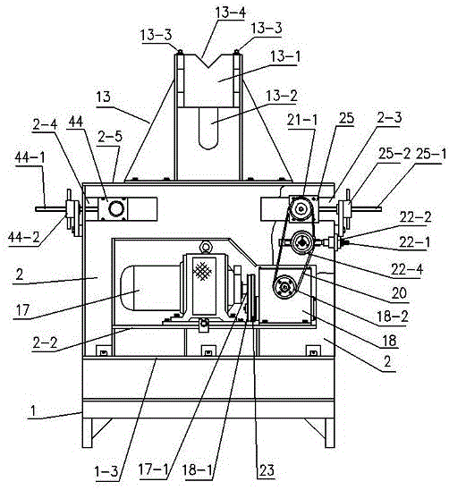
[0121] Such as Figures 5 to 7As shown, the base 1 is a rectangular frame, the bot...


PUM


Abstract

Provided is a double-station winding machine for a high-tension coil of a three-dimensional wound core dry type transformer. The winding machine comprises a base, a left wallboard, a left rack, a right wallboard, a right rack, a winding power device on the left wallboard, a left riding wheel supporting plate mechanism on the left rack, a right riding wheel supporting plate mechanism on the left rack, a winding power device on the right wallboard, a left riding wheel supporting plate mechanism on the right rack, a right riding wheel supporting plate mechanism on the right rack, an iron core support frame, and an iron core turnover support. Since the winding machine has two sets of independent winding power devices, the machine can wind two phases of coils of a transformer. Since positions of the right wallboard can be moved, the machine is suitable for installation of iron cores of transformers in different sizes. Since the main shaft of the main shaft mechanism of the winding power device can move parallelly, cooperation of a left gear and a right gear on the main shaft and riding wheels which are on the right rack and are corresponding to the left gear and the right gear is convenient and reliable, and a gap between a low-voltage inner wall of a transformer winding former and a core limb in rotation can be easily ensured. The device is simple in structure, convenient in operation, high in winding efficiency, and is safe and practical.

Description

technical field [0001] The invention relates to a transformer coil winding machine, in particular to a two-position winding machine for a three-dimensional wound core dry-type transformer high-voltage coil. Background technique [0002] A three-dimensional wound core resin cast dry-type transformer. The high-voltage coil is a segmented layer structure. When winding, the adjacent coil segments need to be wound separately: First, several coils with the same starting end position in the high-voltage coil are wound. Then several coil segments connected in series adjacent to it in the high-voltage coil are reversely wound, so that the winding directions of the two adjacent coil segments can be the same, and can be connected in series in sequence. [0003] If a conventional single-phase winding machine is used to wind such segmented layered coils, it is more cumbersome, because the single-phase winding machine has only one winding station, and the high-voltage coil can only be wou...

Claims


Application Information

Patent Timeline
IPC IPC(8): H01F41/06
Inventor 吴泉舒建华
Owner JIANGXI HANS POWER TECH
Why Eureka
Try Eureka