Atomizer nozzle for a sanitary water outlet and sanitary outlet fitting with a water outlet

A technology of atomizing nozzles and water outlet devices, which is applied in the field of sanitary water outlet accessories, and can solve problems such as complex structures and increased difficulty

Active Publication Date: 2015-10-28
NEOPERL
View PDF8 Cites 2 Cited by
  • Summary
  • Abstract
  • Description
  • Claims
  • Application Information

AI Technical Summary

Problems solved by technology

But this known device has relatively complicated structure, and this structure can increase the difficulty of device manufacture

Method used


Image

  • Atomizer nozzle for a sanitary water outlet and sanitary outlet fitting with a water outlet
  • Atomizer nozzle for a sanitary water outlet and sanitary outlet fitting with a water outlet
  • Atomizer nozzle for a sanitary water outlet and sanitary outlet fitting with a water outlet

Examples


Embodiment Construction

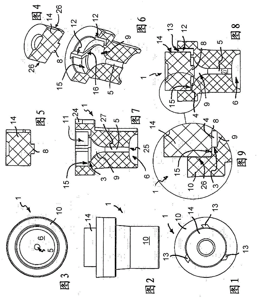
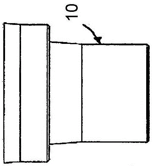
[0060] exist Figures 1 to 16 shows an atomizing nozzle 1 which is used in a sanitary water outlet to atomize water under pressure. The atomizing nozzle 1 should form a uniform water jet with a large volume from a small volume flow.

[0061] The atomizing nozzle 1 has a swirl chamber 2 which, on the inflow side, has a chamber section 3 with an approximately cylindrical or disk-shaped clear cross-section. At least one supply channel 4 oriented transversely and preferably perpendicularly to the longitudinal axis of the nozzle and tangentially into the swirl chamber 2 opens into the swirl chamber 2 .

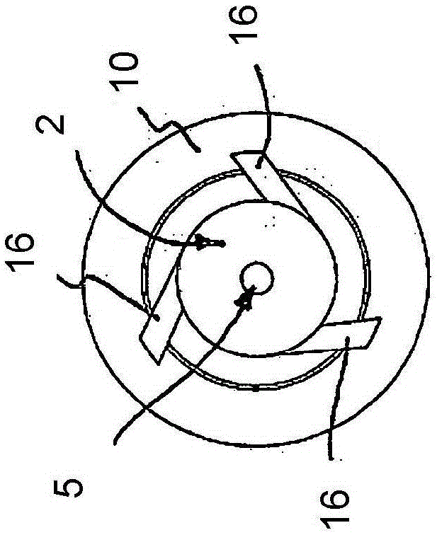
[0062] Such as Figure 11 Visible in the top view of , which shows grooves 16 each forming a supply channel, here a plurality of supply channels 4 open into the vortex chamber 2 , said supply channels being evenly spaced apart from one another in the circumferential direction. The vortex chamber 2 tapers funnel-shaped in the outflow direction in the direction of the nozzle chann...


PUM


Abstract

The invention relates to an atomizer nozzle (1) for a sanitary water outlet, which atomizer nozzle (1) is intended for atomizing water under pressure. The characterizing feature of the atomizer nozzle (1) according to the invention is that the atomizer nozzle (1) has a swirl chamber (2), in which at least a feed channel (4) that is oriented transversely in relation to the longitudinal axis of the nozzle and runs approximately tangentially into the swirl chamber (2) opens out, wherein the swirl chamber (2) tapers in the outflow direction, in the direction of a nozzle channel (5). The atomizer nozzle (1) can be used to produce a water jet of a homogeneous jet pattern that gives the impression of a voluminous water jet in spite of having a low volumetric flow.

Description

technical field [0001] The invention relates to an atomizing nozzle for a sanitary water outlet for atomizing water under pressure. [0002] The invention also relates to a sanitary water outlet fitting with a water outlet device. Background technique [0003] WO 2012 / 055051 A1 already discloses a device for spraying pressurized liquid which can be used as an outlet piece for a sanitary fitting or as a shower head. The known device has a central supply channel for the liquid which extends along the device axis. A plurality of swirl chambers are arranged at intervals around the device axis, each having an inlet for feeding liquid into the respective swirl chamber and an outlet nozzle for a liquid jet leaving the swirl chamber. The swirl chamber is connected to the supply channel via an inflow channel, which is arranged approximately transversely to the device axis. Each outlet nozzle is arranged obliquely to the longitudinal axis of the device in such a way that the liquid...

Claims


Application Information

Patent Timeline
Patent Type & Authority Applications(China)
IPC IPC(8): B05B1/34B05B1/18E03C1/086
CPCB05B1/3436B05B1/185E03C1/0409E03C1/08B05B1/06E03C1/0408
Inventor H·许尔勒
Owner NEOPERL
Why Eureka
Try Eureka