A riveting equipment for automatic blanking

An automatic blanking and equipment technology, which is applied to metal processing equipment, feeding devices, positioning devices, etc., can solve the problems of small nail tails and weak connections, etc., achieve good safety performance, improve labor efficiency, and save labor costs. Effect

Inactive Publication Date: 2017-03-08
HAIYAN HONGQIANG HARDWARE MFG CO LTD
View PDF8 Cites 0 Cited by
  • Summary
  • Abstract
  • Description
  • Claims
  • Application Information

AI Technical Summary

Problems solved by technology

[0004] Nails are widely used in daily life as a tool for connecting and fixing two objects, but the tails of the nails are relatively small, and sometimes it is easy to embed into the object to make the connection weak. Large area to reduce the effect of pressure, but the current nails are not able to meet these requirements or overcome these shortcomings, so people think of punching a hole in the iron sheet to make the nail and the iron sheet riveted together so that the shape of the nail can be changed to form a new tools, thereby expanding the scope of use of nails and making it possible to overcome some shortcomings of nails, but to rivet nails and iron sheets together, the existing riveting equipment does not have similar special riveting equipment, so it is necessary to propose a Riveting equipment for riveting nails and iron sheets

Method used


Image

  • A riveting equipment for automatic blanking
  • A riveting equipment for automatic blanking
  • A riveting equipment for automatic blanking

Examples


Embodiment Construction

[0021] In order to make the object, technical solution and advantages of the present invention clearer, the present invention will be further described in detail below with reference to the accompanying drawings and embodiments. However, it should be understood that the specific embodiments described here are only used to explain the present invention, and are not intended to limit the scope of the present invention. Also, in the following description, descriptions of well-known structures and techniques are omitted to avoid unnecessarily obscuring the concept of the present invention.

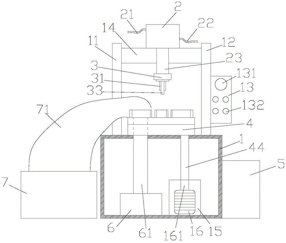
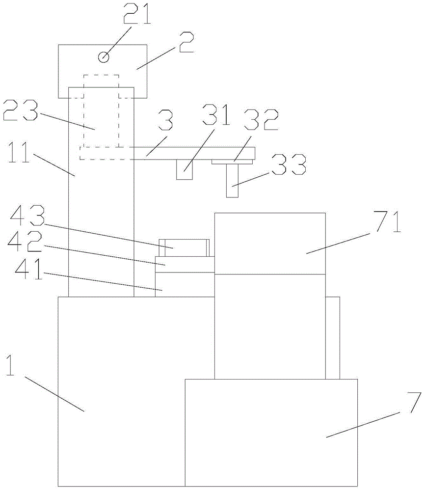
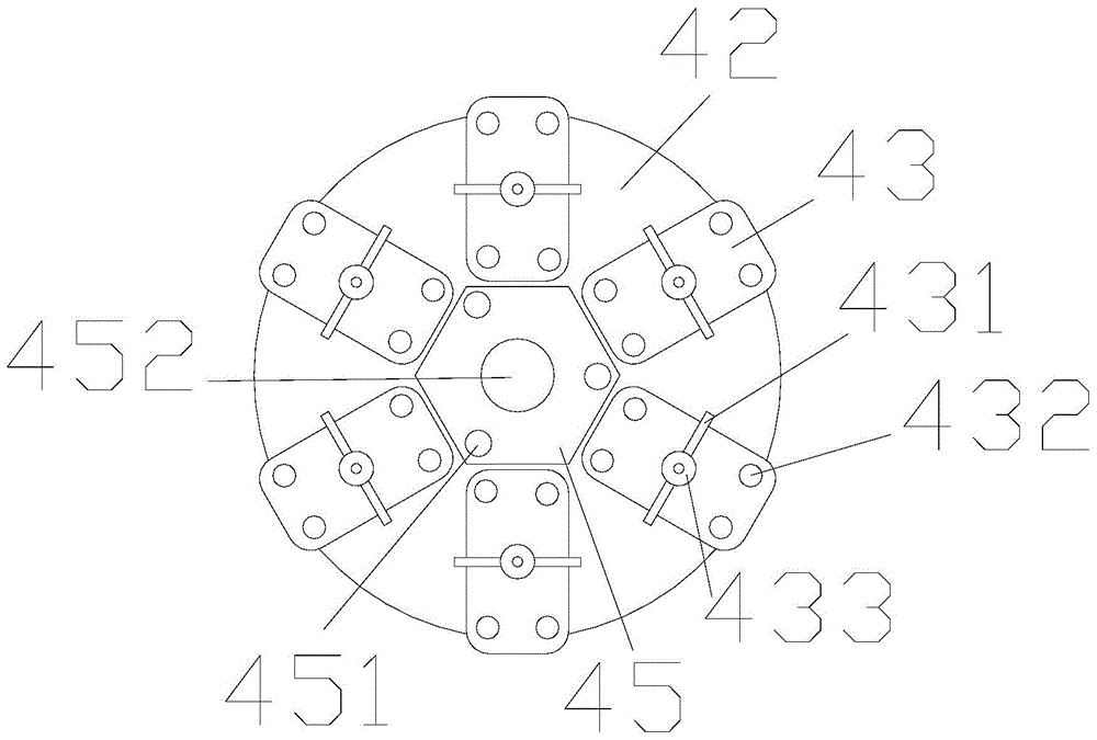
[0022] refer to figure 1 , figure 2 with image 3 , the embodiment of the present invention provides a riveting equipment for automatic blanking, including a box body 1, a hydraulic cylinder 2, a pressing device 3, a workbench 4, a hydraulic pump 5, and a blanking box 7. The box body 1 is hollow and located at The bottom of the equipment, the box body 1 also includes a first support plate ...


PUM


Abstract

The invention provides an automatic discharging riveting device. The automatic discharging riveting device comprises a box body, a hydraulic cylinder, a pressing device, a workbench, a hydraulic pump and a discharging box. The box body is hollow and is located at the bottom of the device. The box body further comprises a first supporting plate, a second supporting plate, a controller and a cross beam. The controller further comprises a scram button and a control button. The hydraulic cylinder further comprises an oil inlet pipe, an oil outlet pipe and a hydraulic shaft. The lower end of the hydraulic shaft is connected with the pressing device. The workbench is arranged on the upper surface of the box body. The hydraulic pump is located on the right side of the box body. The oil inlet pipe and the oil outlet pipe are connected with the hydraulic pump. The upper end of the discharging box is further provided with a discharging channel. The discharging channel is in an arc shape. An opening in the other end is located above the workbench. According to the automatic discharging riveting device, the riveting theory is simple, the riveting quality is good, the structure is simple, the operation is convenient, the safety performance is good, automatic discharging can be achieved, the labor cost is greatly saved, and the labor efficiency is improved.

Description

[0001] 【Technical field】 [0002] The invention relates to riveting equipment, in particular to a riveting equipment for automatic blanking. [0003] 【Background technique】 [0004] Nails are widely used in daily life as a tool for connecting and fixing two objects, but the tails of the nails are relatively small, and sometimes it is easy to embed into the object to make the connection weak. Large area to reduce the effect of pressure, but the current nails are not able to meet these requirements or overcome these shortcomings, so people think of punching a hole in the iron sheet to make the nail and the iron sheet riveted together so that the shape of the nail can be changed to form a new tools, thereby expanding the scope of use of nails and making it possible to overcome some shortcomings of nails, but to rivet nails and iron sheets together, the existing riveting equipment does not have similar special riveting equipment, so it is necessary to propose a Riveting equipment ...

Claims


Application Information

Patent Timeline
Patent Type & Authority Patents(China)
IPC IPC(8): B21D39/00B21D43/20
Inventor 钟岳祥
Owner HAIYAN HONGQIANG HARDWARE MFG CO LTD
Why Eureka
Try Eureka