
A Welding Fixture for Multifunctional Door Shaft

A welding fixture and multi-functional technology, applied in the field of welding fixtures for multifunctional door shafts, can solve the problems that the verticality of the connecting arm of the door shaft cannot be guaranteed, waste products are easy to be generated, and the docking is difficult, etc., and the welding effect is good, the quality is high, adaptable effect

Active Publication Date: 2016-08-17
SPRING ELECTRONICS WUJIANG
View PDF8 Cites 0 Cited by
  • Summary
  • Abstract
  • Description
  • Claims
  • Application Information

AI Technical Summary

Problems solved by technology

[0002] In the cabinet cabinet, the door shaft is an important part. Due to the different installation positions of many door shafts, there are considerable differences in their structural shapes. For a door shaft composed of a main shaft, a door shaft connecting arm and a connecting shaft In other words, since the connecting arm of the door shaft is vertically arranged on the outer surface of the main shaft, its connecting surface is arc-shaped, and the width of the joint is only the thickness of the connecting arm of the door shaft, so the butt joint is difficult, and the connection of the door shaft cannot be guaranteed during welding. The verticality of the arm is easy to produce waste products and the production efficiency is extremely low

Method used


Image

  • A Welding Fixture for Multifunctional Door Shaft
  • A Welding Fixture for Multifunctional Door Shaft
  • A Welding Fixture for Multifunctional Door Shaft

Examples


Embodiment Construction

[0020] The following will clearly and completely describe the technical solutions in the embodiments of the present invention with reference to the accompanying drawings in the embodiments of the present invention. Obviously, the described embodiments are only some, not all, embodiments of the present invention. Based on the embodiments of the present invention, all other embodiments obtained by persons of ordinary skill in the art without creative efforts fall within the protection scope of the present invention.

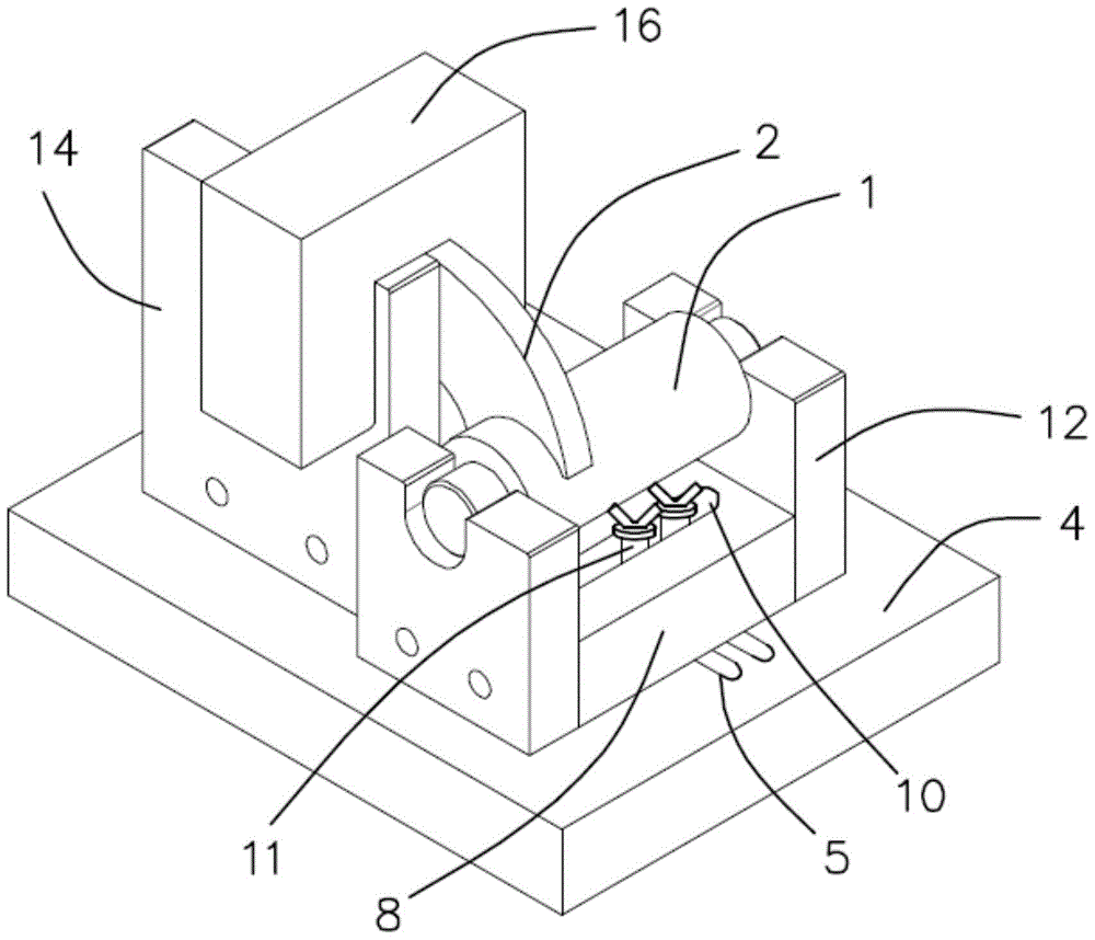
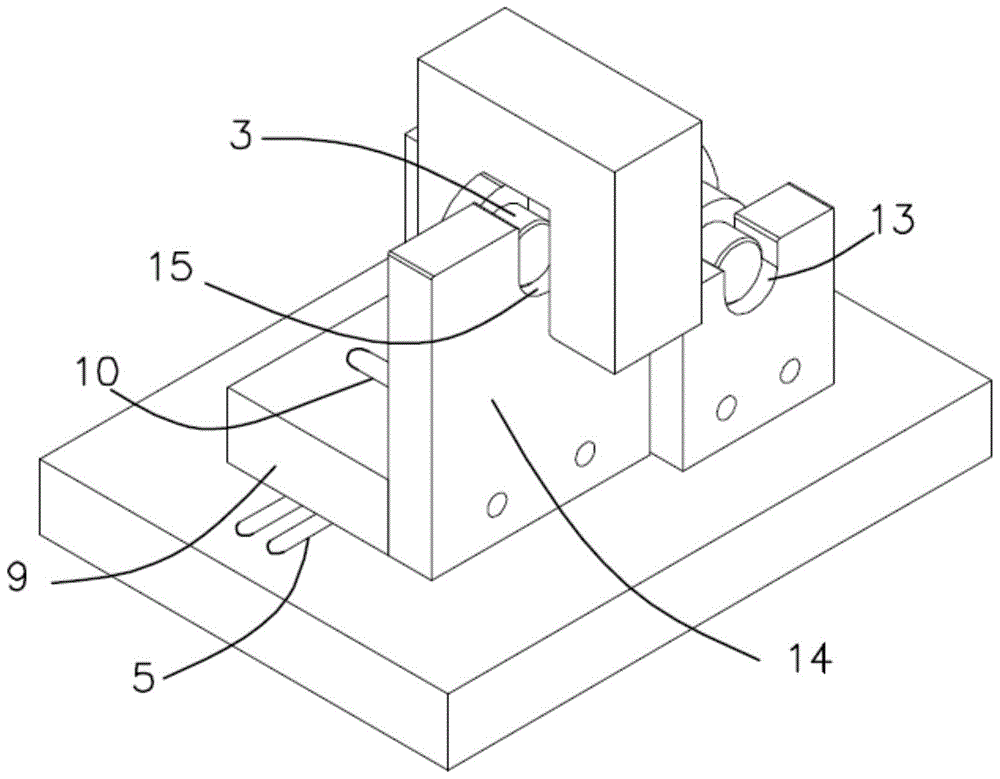
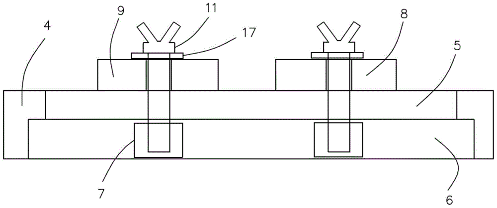
[0021] refer to Figure 1 to Figure 3 As shown, a welding fixture for a multi-functional door shaft, the door shaft is composed of a main shaft 1, a door shaft connecting arm 2 and a connecting shaft 3, the door shaft connecting arm and the connecting shaft are an integral structure, including a base 4, and the base surface is arranged in parallel There are two transverse guide grooves 5, the bottom of the transverse guide groove is provided with a nut fixing groov...


PUM


Abstract

The invention discloses a welding clamp for a multifunctional door shaft. The welding clamp comprises a base. Two transverse guiding grooves are formed in the surface of the base in parallel. A nut fixing groove is formed at the bottoms of the transverse guiding grooves. A hexagon nut is arranged in the nut fixing groove. The transverse guiding grooves are provided with a main shaft erecting plate and a connecting shaft erecting plate which are each provided with a longitudinal guiding groove. The longitudinal guiding grooves are internally provided with two butterfly bolts. The butterfly bolts penetrate the longitudinal guiding grooves and the transverse guiding grooves and are in threaded connection with the hexagon nut. Main shaft fixing plates are arranged on the two sides of the main shaft erecting plate respectively. First arc erecting grooves are formed in the middles of the tops of the main shaft fixing plates. A connecting shaft fixing plate is arranged on the side face of the connecting shaft erecting plate. A second arc erecting groove is formed in the top of the connecting shaft fixing plate. A concave clamping plate is arranged on the top of the connecting shaft fixing plate. The welding clamp is simple in structure, reasonable in design, convenient to use, high in adaptability, low in welding difficulty and high in yield.

Description

technical field [0001] The invention relates to the field of fixtures, in particular to a welding fixture for a multifunctional door shaft. Background technique [0002] In the cabinet cabinet, the door shaft is an important part. Due to the different installation positions of many door shafts, there are considerable differences in their structural shapes. For a door shaft composed of a main shaft, a door shaft connecting arm and a connecting shaft In other words, since the connecting arm of the door shaft is vertically arranged on the outer surface of the main shaft, its connecting surface is arc-shaped, and the width of the joint is only the thickness of the connecting arm of the door shaft, so the butt joint is difficult, and the connection of the door shaft cannot be guaranteed during welding. The verticality of the arm is prone to waste, and the production efficiency is extremely low. Contents of the invention [0003] The purpose of the present invention is to overc...

Claims


Application Information

Patent Timeline
Patent Type & Authority Patents(China)
IPC IPC(8): B23K37/04
CPCB23K37/0443
Inventor 江海社
Owner SPRING ELECTRONICS WUJIANG
Learn More