Blade clamping structure of novel plate shearing machine

A technology of clamping structure and shearing machine, applied in the direction of clamping, shearing device, shearing machine equipment, etc., can solve the problems of complex tool adjustment structure, difficult blade adjustment, and difficult adjustment of tool gap, so as to reduce the manual assembly time , make up for straightness defects, and have a high degree of interchangeability

Inactive Publication Date: 2015-11-04
CHANGZHOU ZEMU MACHINERY TECH CO LTD
View PDF0 Cites 4 Cited by
  • Summary
  • Abstract
  • Description
  • Claims
  • Application Information

AI Technical Summary

Problems solved by technology

[0002] In the machining industry, the development of cutting tools has entered the era of the development of mechanical clamping tools, but most of the machine clamping tools used in the machining industry currently have the following two problems: one is due to the clamping and adjustment of the blade. Complexity makes it difficult to manufacture the tool, the number of teeth that can be arranged is small, the operation is inconvenient in actual use, and the cutting efficiency is difficult to improve; secondly, due to the complex structure of the tool adjustment, the adjustment of the blade is difficult, time-consuming and laborious, and the tool clearance is difficult to adjust. Affecting the straightness of the machining tool can lead to abnormal wear of the tool, reduced service life, and also affects the production quality of the finished product; the third is that the existing blade is directly fixed on the tool holder with screws when assembling. High requirements are placed on both assembly and post-tool change

Method used


Image

  • Blade clamping structure of novel plate shearing machine

Examples


Embodiment Construction

[0015] All features disclosed in this specification, or steps in all methods or processes disclosed, may be combined in any manner, except for mutually exclusive features and / or steps.

[0016] Any feature disclosed in this specification (including any appended claims, abstract and drawings), unless expressly stated otherwise, may be replaced by alternative features which are equivalent or serve a similar purpose. That is, unless expressly stated otherwise, each feature is one example only of a series of equivalent or similar features.

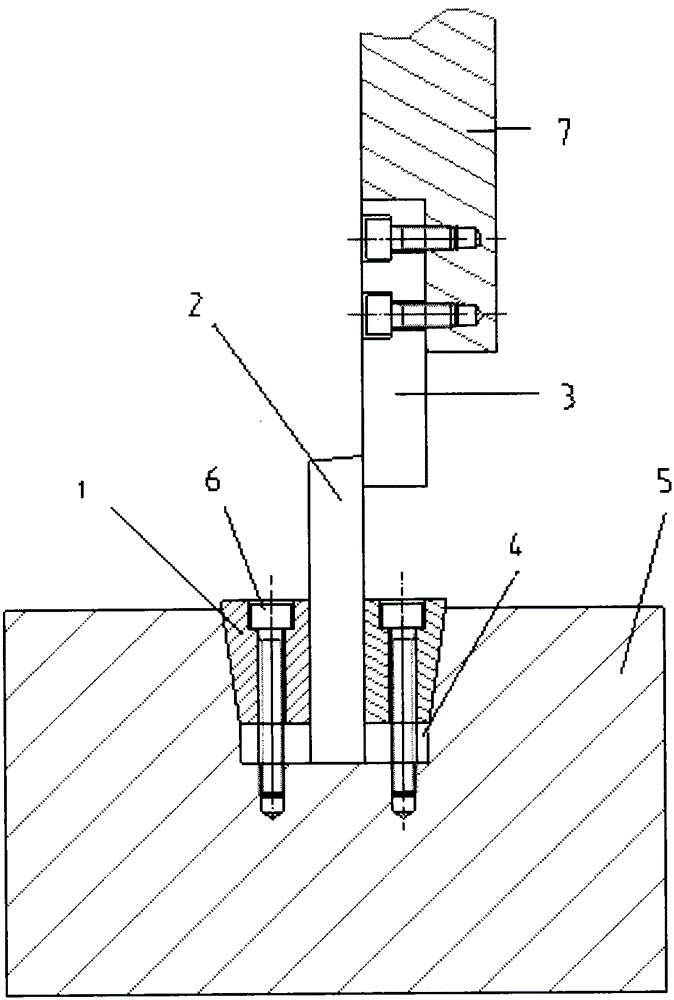
[0017] Such as figure 1 As shown, a novel shearing machine blade clamping structure includes an upper blade 3, a lower blade 2, and a base 5, and the left and right sides of the lower blade 2 are respectively provided with wedge-shaped blocks, and the wedge-shaped blocks are inclined wedges 1 . The edge of the lower blade 2 is provided with a matching upper blade 3, and the upper blade 3 is fixed on the knife rest 7 by screws; the base 5 is ...


PUM


Abstract

The invention relates to a blade clamping structure of a novel plate shearing machine. The structure comprises an upper blade, a lower blade and a base, wherein a groove is formed in the base; the lower blade is arranged in the groove; wedged blocks are respectively arranged at the left and right sides of the lower blade; and the upper blade fitting the lower blade is arranged in an edge of the lower blade. At present, in the assembly of blades in general plate shearing machines, the blades are directly fixed on a tool post by using screws, so that the requirements on assembly and later tool replacement are higher; and the tool adjusting structure is complex, so that the blade adjustment is troublesome, both time and labor are wasted, and the tool gap is difficultly adjusted. The lower blade is free of screw holes; the installation positioning and the gap adjustment are both dependent on a mutual locking effect of the V-shaped groove and the inclined wedges, so that the effects of stability and reliability are achieved, the manual assembly time is shortened, and the tool replacement degree is high; and in addition, the structure has such characteristics as easy adjustment of the tool gap, capability of making up the straightness defect in the tool machining and convenience for tool installation and disassembly.

Description

technical field [0001] The invention relates to the technical field of corrugated sheet shearing machines, in particular to a novel shearing machine blade clamping structure. Background technique [0002] In the machining industry, the development of cutting tools has entered the era of the development of mechanical clamping tools, but most of the machine clamping tools used in the machining industry currently have the following two problems: one is due to the clamping and adjustment of the blade. Complexity makes it difficult to manufacture the tool, the number of teeth that can be arranged is small, the operation is inconvenient in actual use, and the cutting efficiency is difficult to improve; secondly, due to the complex structure of the tool adjustment, the adjustment of the blade is difficult, time-consuming and laborious, and the tool clearance is difficult to adjust. Affecting the straightness of the machining tool can lead to abnormal wear of the tool, reduced servi...

Claims


Application Information

Patent Timeline
IPC IPC(8): B23Q3/00B23D15/06
CPCB23Q3/00B23D15/06
Inventor 张文波
Owner CHANGZHOU ZEMU MACHINERY TECH CO LTD
Why Eureka
Try Eureka