Amphibious aircraft with wave inhibition groove outer plate

A technology for amphibious aircraft and wave suppression tanks, which is applied to seaplanes, aircraft, motor vehicles, etc. It can solve problems such as serious splashing, deformation and damage of components, and achieve improved splashing performance, improved seakeeping, and increased attendance rate effect

Active Publication Date: 2015-11-04
CHINA SPECIAL TYPE FLIER RES INST
View PDF7 Cites 2 Cited by
  • Summary
  • Abstract
  • Description
  • Claims
  • Application Information

AI Technical Summary

Problems solved by technology

[0003] The purpose of the present invention is aimed at the current, amphibious aircraft in the process of taking off from the water surface, which produces a large amount of high-speed splashing water flow, and these splashing water flows will impact the aircraft power plant, flaps, and empennage, which not only makes these parts deform and cannot be normal. Use, even direct damage occurs, and the impact of the water for a long time will also corrode the above-mentioned structure. In the wave state, the splashing situation is more serious, and an amphibious aircraft with the outer plate of the wave suppression groove is provided.

Method used


Image

  • Amphibious aircraft with wave inhibition groove outer plate
  • Amphibious aircraft with wave inhibition groove outer plate

Examples


Embodiment Construction

[0012] Such as figure 1 , 2 As shown, the present invention includes an amphibious aircraft body 1, which also has a wave suppression tank outer plate 2 and a set of connecting rods 3, and the wave suppression tank outer plate 2 is installed on the bottom of the amphibious aircraft body 1 through a set of connecting rods 3, and The wave suppression groove 1-1 is formed with the fuselage of the amphibious aircraft body 1.

[0013] The outer plate 2 of the anti-wave groove has a group of decompression holes.

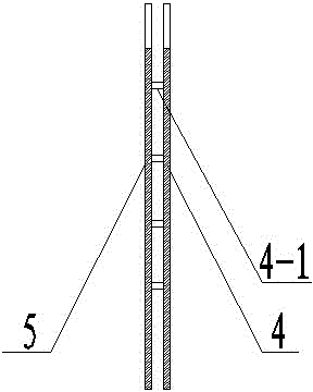
[0014] The outer plate 2 of the wave suppression tank includes an outer plate 4 and an inner plate 5, and the outer plate 4 is installed on the inner plate 5 through a set of connecting shafts 4-1.

[0015] The outer plate 4 and the inner plate 5 are metal plates.

[0016] Working principle: The outer plate of the wave suppression groove and the hull of the aircraft form a groove, that is, the wave suppression groove. The splash water generated by the hull enters 1-1 a...


PUM


Abstract

An amphibious aircraft with a wave inhibition groove outer plate comprises an amphibious aircraft body (1) and is further provided with a wave inhibition groove outer plate (2) and a group of connecting rods (3). The wave inhibition groove outer plate (2) is installed at the bottom of the amphibious aircraft body (1) through the group of connecting rods (3) and forms a wave inhibition groove (1-1) together with a fuselage of the amphibious aircraft body (1). The amphibious aircraft has the advantages of remarkably improving spattering performance, enhancing seakeeping capacity, and improving attendance rate.

Description

technical field [0001] The invention relates to the field of amphibious aircraft production, in particular to an amphibious aircraft with an outer plate of a wave suppression groove. Background technique [0002] At present, during the take-off of an amphibious aircraft on the water surface, a large amount of high-speed splashing water is generated. These splashing waters will impact the aircraft power plant, flaps, and empennage. This not only makes these parts deform and cannot be used normally, but even directly Damage, and the impact of water flow for a long time will also corrode the above structure, and the splashing situation is more serious in the wave state. Contents of the invention [0003] The purpose of the present invention is aimed at the current, amphibious aircraft in the process of taking off from the water surface, which produces a large amount of high-speed splashing water flow, and these splashing water flows will impact the aircraft power plant, flap...

Claims


Application Information

Patent Timeline
Patent Type & Authority Applications(China)
IPC IPC(8): B64C35/02
Inventor 唐彬彬吴彬左仔滨王丽丽王颖翔黄淼
Owner CHINA SPECIAL TYPE FLIER RES INST
Why Eureka
Try Eureka