Intelligent projector
A smart projector and image technology, applied in the field of smart projectors, can solve problems such as navigator looking down at navigation, traffic accident defects, etc., and achieve the effect of avoiding interruption of attention
- Summary
- Abstract
- Description
- Claims
- Application Information
AI Technical Summary
Problems solved by technology
Method used
Image
Examples
Embodiment 1
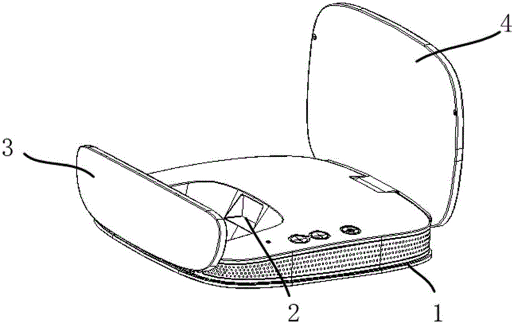
[0025] figure 1 Shown is a smart projector, as a vehicle-mounted multimedia player, used to play traffic information, song lyrics and other content to the user, wherein the playback content is stored in the vehicle control system or other equipment in the form of a signal source (such as In the USB storage device, it is connected to the vehicle system through the USB interface).
[0026] The intelligent projector of the present invention comprises: machine box 1; Be arranged on the machine box 1, be used for playing the optical machine 2 of signal source; Be arranged on the imaging screen 3 and reflective screen 4 at the opposite side walls of machine box 1, wherein The imaging screen 3 is used to receive the signal source and display the image on the imaging surface, and the reflective screen 4 is used to receive the image projected by the imaging screen 3 and reflect the image, so that the user can directly view the reflective screen 4 to obtain the required information.
...
Embodiment 2
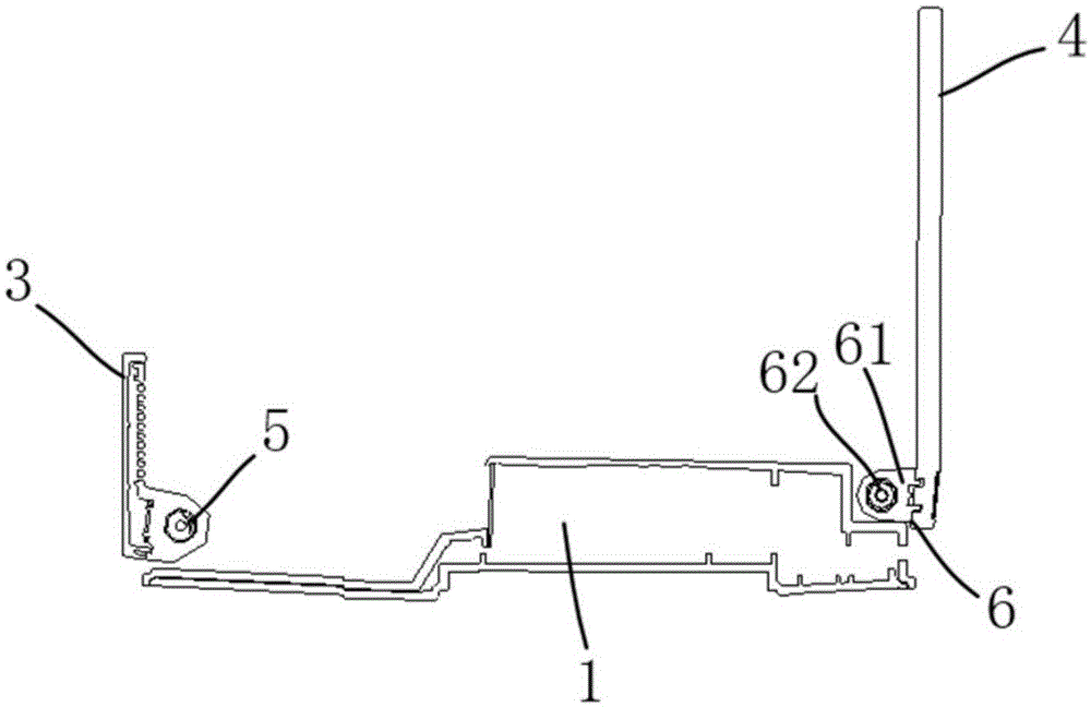
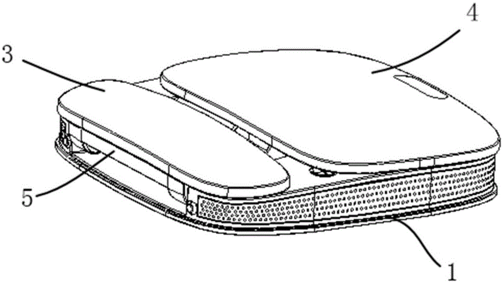
[0030] The difference between Embodiment 2 and Embodiment 1 is that the smart projector also includes a first connection mechanism 5 and a second connection mechanism 6, such as figure 2 As shown, the imaging screen 3 is connected to the machine box 1 through the first connecting mechanism 5 , and the reflective screen 4 is connected to the machine box 1 through the second connecting mechanism 6 . When in the non-working state, the imaging screen 3 and the reflective screen 4 can be combined on the machine box 1 through the connecting mechanism, such as image 3 As shown, in the working state, it can be opened relatively to perform imaging and reflection of the signal source. Through the first connection mechanism 5 and the second connection mechanism 6, the imaging screen 3 and the reflection screen 4 are movably arranged on two opposite sides of the machine box 1, respectively. When in the non-working state, the imaging screen 3 and the reflective screen 4 are closed along...
Embodiment 3
[0035] The smart projector in embodiment 3 is basically the same as embodiment 1 and embodiment 2, the difference is that the smart projector also includes a focusing gear 7 for adjusting the optical-mechanical focal length, such as Figure 4 As shown, it is used to adjust the focal length according to the distance between the imaging screen 3 and the optical machine 2 . The focusing gear 7 can be arranged at any position, and in a preferred solution, the focusing gear 7 is arranged on the case 1 . Due to physiological or external reasons, there will always be gaps in vision between people, and they have different perceptions of the images presented. Therefore, the size and definition of the signal source emitted by the optical machine 2 to the imaging screen 3 are adjusted through the focusing gear 7, which meets the needs of different users for the smart projector.
PUM
 Abstract
Description
Claims
Application Information
 - R&D
- Intellectual Property
- Life Sciences
- Materials
- Tech Scout
- Unparalleled Data Quality
- Higher Quality Content
- 60% Fewer Hallucinations
Browse by: Latest US Patents, China's latest patents, Technical Efficacy Thesaurus, Application Domain, Technology Topic, Popular Technical Reports.
© 2025 PatSnap. All rights reserved.Legal|Privacy policy|Modern Slavery Act Transparency Statement|Sitemap|About US| Contact US: help@patsnap.com


