Check patentability & draft patents in minutes with Patsnap Eureka AI!

Stop device

A technology of stopper device and stopper rod is applied in the field of metal belt collection auxiliary devices, which can solve the problems of metal belt scattering affecting the normal operation of the machine, scratches, and easy scratching of metal belts.

Active Publication Date: 2015-11-11
SUZHOU SHENGXIN OPTOELECTRONICS TECH
View PDF6 Cites 1 Cited by
  • Summary
  • Abstract
  • Description
  • Claims
  • Application Information

AI Technical Summary

Problems solved by technology

[0002] At present, in the process of collecting metal strips, due to the influence of the characteristics of the metal strip itself, for example, when it is collected in the take-up reel, the metal strip is easy to scatter, and when it is collected more, the metal strip is easy to fall off the take-up reel. In this way, the metal strips will be scattered and affect the normal operation of the matching machine. More importantly, the scattered metal strips are easily scratched when they are collected again, resulting in scratches and affecting the quality.

Method used


Image

  • Stop device

Examples


Embodiment Construction

[0022] Specific embodiments of the present invention will be described in detail below in conjunction with the accompanying drawings. It should be understood that the specific embodiments described here are only used to illustrate and explain the present invention, and are not intended to limit the present invention.

[0023] In the present invention, in the absence of a contrary statement, the orientation words included in the term such as "up, down, left, right, inside, outside" only represent the orientation of the term in the normal use state, or for the purpose of A common term understood by those skilled in the art, and should not be considered as a limitation of the term.

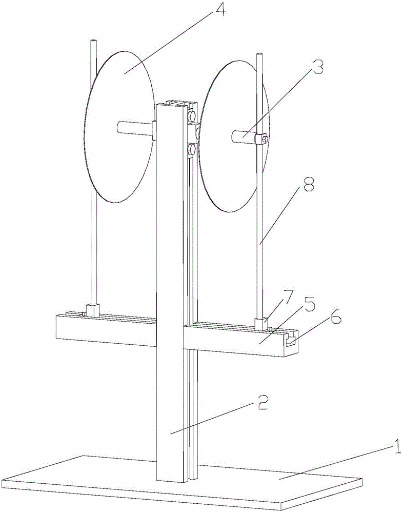
[0024] The invention provides a stop device, such as figure 1 As shown, the stop device includes a base plate 1, a support rod 2, two telescopic rods 3, two take-up reels 4, two stop rods 8 and two cross bars 5; the support rod 2 is installed vertically On the base plate 1; the telescopic rod 3 and...


PUM


Abstract

The invention discloses a stop device which comprises a bottom plate, a support rod, two telescopic rods, two take-up reels, two stop rods and two transverse rods. The support rod is vertically installed on the bottom plate; the telescopic rods and the transverse rods are vertically connected to the support rod, the telescopic rods are arranged on the two opposite sides of the support rod, and the transverse rods are arranged on the two opposite sides of the support rod; the take-up reels are rotatably arranged on the telescopic rods in a penetrating mode; the stop rods are movably connected with fastening pieces in a sleeved mode, the fastening pieces are detachably connected to the end faces of the telescopic rods, and the stop rods are slidably arranged on the transverse rods. According to the stop device, a metal strip cannot be disengaged from the take-up reels, and the quality of the metal strip is guaranteed.

Description

technical field [0001] The invention relates to an auxiliary device for collecting metal strips, in particular to a stopper device. Background technique [0002] At present, in the process of collecting metal strips, due to the influence of the characteristics of the metal strip itself, for example, when it is collected in the take-up reel, the metal strip is easy to scatter, and when it is collected more, the metal strip is easy to fall off the take-up reel. Like this, can make the normal operation of the machine that the metal strip is scattered affect it to match, more importantly, when the scattered metal strip is collected again easily scratches, produces scratches, affects quality. [0003] Therefore, it is an urgent problem to be solved in the present invention to provide a stop device that can prevent the metal strip from falling off from the take-up reel. Contents of the invention [0004] The purpose of the present invention is to provide a stop device that can ...

Claims


Application Information

Patent Timeline
IPC IPC(8): B65H18/02
CPCB65H18/02B65H2301/414B65H2402/30
Inventor 鲍启兵李义洪术茂纪沿海
Owner SUZHOU SHENGXIN OPTOELECTRONICS TECH
Features
  • R&D
  • Intellectual Property
  • Life Sciences
  • Materials
  • Tech Scout
  • Unparalleled Data Quality
  • Higher Quality Content
  • 60% Fewer Hallucinations
Learn More